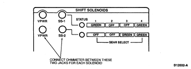
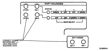
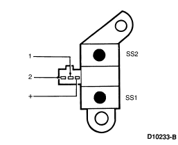
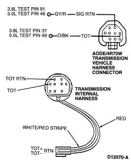
If DTCs are present while performing the On-Board Diagnostics, refer to
the On-Board Diagnostic Trouble Code Description Chart for the appropriate
service procedure. Prior to entering Pinpoint Tests, refer to any TSBs and
Oasis messages for AODE transmission concerns.
| *Output circuit check, generated only by electrical symptoms. |
| **May also be generated by some other non-electric transmission
hardware system. |
| Three Digit DTCa
|
Four Digit DTCb
|
Component |
Description |
Condition |
Symptom |
Action |
| 111 |
P1111 |
SYSTEM |
Pass |
No malfunction detected. |
Malfunction not
detected by PCM. |
PC/ED |
112
113 |
P0112
P0113 |
IAT |
IAT indicates 125°C (254°F) (grounded)
IAT indicates -40°C (-40°F) (open circuit) |
Voltage drop across IAT exceeds scale set for temperature 125°
C (254°F).
Voltage drop across IAT exceeds scale set for
temperature -40°C (-40°F). |
Incorrect EPC
pressure. Either high or low which will result in harsh or soft shifts. |
PC/ED |
| 114 |
P0114 |
IAT |
IAT out of on-board diagnostic range |
IAT temperature higher or lower
than expected during KOEO and KOER. |
Rerun on-board diagnostic at normal
operating temperature. |
PC/ED |
| 116 |
P1116 |
IAT |
ECT out of on-board diagnostic range |
ECT temperature
higher or lower than expected during KOEO and KOER. |
Rerun on-board diagnostic
at normal operating temperature. |
PC/ED |
117
118 |
P0117
P0118 |
ECT |
ECT indicates 125°C
(254°F)
ECT indicates -40°C
(-40°F) |
Voltage drop across ECT exceeds scale set for
temperature 125°C (254°F) (grounded).
Voltage drop across ECT exceeds scale set for temperature -40°
C (-40°F) (open circuit). |
Torque converter clutch will
always be off, resulting in reduced fuel economy. |
PC/ED |
| 121 |
P1124 |
TP |
TP voltage high/low for on-board diagnostic. |
TP was not
in the correct position for on-board diagnostic. |
Rerun at appropriate
throttle position per application. |
PC/ED |
| 122, 123, 124, 125, 167 |
P0122, P0123, P1120, P1121, P1125 |
TP |
TP concern |
PCM has detected an
error. This error may cause a transmission concern. |
Harsh engagements, firm
shift feel, abnormal shift schedule, torque converter clutch does not engage.
Torque converter clutch cycling. |
PC/ED |
| 157, 158, 159, 184, 185 |
P0102, P0103, P1100, P1101 |
MAF |
MAF concerns |
MAF system has a malfunction which may cause a
transmission concern. |
High/low EPC pressure, incorrect shift schedule.
Incorrect torque converter clutch engagement scheduling. Symptoms similar to a
TP failure. |
PC/ED |
212
211-219
221-224
232-239
241-243 |
P0300-P0308
P0320, P0340
P1351-P1364 |
ICM |
ICM concerns |
ICM system has a malfunction which may cause a transmission concern. |
Harsh engagements and shifts, late WOT shifts, no torque converter clutch
engagement. |
PC/ED |
| 452 |
P0500 |
VSS |
Insufficient input from VSS. |
PCM detected a loss of vehicle speed
signal during operation. |
Torque converter clutch engages, shift
engagement/disengagement (hunting) on grades. |
PC/ED |
| 522 |
P1709 |
MLP |
MLP not in PARK. |
On-board diagnostic not run in PARK. |
Rerun
on-board diagnostic in PARK. |
Refer to Pinpoint Test D. |
| 536 |
P1703 |
BOO |
Brake not actuated during on-board diagnostic.
BOO switch circuit
failed. |
Brake not cycled during KOER.
Brake ON/OFF circuit failure. |
Failed ON or not connected— torque converter clutch will not
engage at less than 1/3 throttle.
Failed OFF or not
connected— torque converter clutch will not disengage when brake
is applied. |
PC/ED |
| 539 |
P1460 |
A/C |
A/C clutch cycling pressure switch error |
A/C or Defrost ON condition may result from A/C clutch being ON during on-board diagnostic. |
DTC set during on-board diagnostic— rerun TOT—A/C
OFF.
Failed ON—EPC pressure slightly low with A/C OFF. |
PC/ED |
| 617** |
P1731** |
SS1 or internal parts |
1-2 shift error |
Engine rpm drop not detected when 1-2 shift was commanded by PCM. |
Improper gear selection depending on failure or mode and manual lever
position. Shift errors may also be due to other internal transmission concerns
(stuck valves, damaged friction material). |
Refer to Solenoid On/Off Charts. Refer to Pinpoint Test A. |
| 618** |
P1732** |
SS1, SS2 or internal parts |
2-3 shift error |
Engine rpm drop not detected when 2-3 shift was commanded by PCM. |
Improper gear selection depending on failure or mode and manual lever
position. Shift errors may also be due to other internal transmission concerns
(stuck valves, damaged friction material). |
Refer to Solenoid On/Off Charts. Refer to Pinpoint Test A. |
| 619** |
P1733** |
SS1, SS2 or internal parts |
3-4 shift error |
Engine rpm drop not detected when 3-4 shift was commanded by PCM. |
Improper gear selection depending on failure or mode and manual lever
position. Shift errors may also be due to other internal transmission concerns
(stuck valves, damaged friction material). |
Refer to Solenoid On/Off Charts. Refer to Pinpoint Test A. |
| 621* |
P0750* |
SS1 |
SS1 solenoid circuit failure |
SS1 circuit failed to provide voltage
drop across solenoid. Circuit open or shorted or PCM driver failure during
on-board diagnostic. |
Improper gear selection depending on condition mode and
manual lever position. See Solenoid On/Off chart. |
Refer to Pinpoint Test A |
| 622* |
P0755* |
SS2 |
SS2 solenoid circuit failure |
SS2 circuit fails to provide voltage
drop across solenoid. Circuit open or shorted or PCM driver failure during
on-board diagnostic. |
Improper gear selection depending on condition mode and
manual lever position. See Solenoid On/Off chart. |
Refer to Pinpoint Test A |
| 623 |
TBD |
TCIL |
TCIL circuit failure |
TCIL circuit open or shorted. |
Failed ON—Overdrive cancel mode on. NO flashing TCIL for EPC
or sensor failure.
Failed OFF—Overdrive cancel mode never indicated. NO
flashing TCIL for EPC or sensor failure. |
PC/ED |
| 624* |
P1747** |
EPC |
EPC solenoid circuit failure, shorted circuit or output driver. |
Voltage through EPC solenoid is checked. An error will be noted if tolerance
is exceeded. |
Short Circuit—Causes minimum EPC pressure (minimum capacity)
and limits engine torque (alternate firm). |
Refer to Pinpoint Test E. |
| 625* |
P1746** |
EPC |
Shorted PCM output driver. |
|
Open Circuit—Causes maximum EPC pressure, harsh engagements
and shifts. |
Refer to Pinpoint Test E. |
| 628** |
P0741** |
Transmission |
Transmission slippage detected. |
The PCM picked up an excessive amount of slippage during normal vehicle
operation. |
Transmission slippage/erratic or no torque converter clutch operation. Flash
TCIL. |
Refer to Diagnosis by Symptom. |
| 632 |
P1780 |
TCS |
TCS not changing states. |
TCS not cycled during self-test. TCS circuit open or shorted. |
Rerun on-board diagnostic and cycle switch. No D cancel when switch is cycled. |
PC/ED |
| 634 |
P1709 |
MLP |
MLP out of range. |
Indicated voltage drop across MLP exceeds limits
established for each position. |
Harsh engagements, firm shift feel.
No 3/4
shift. |
Refer to Pinpoint Test D. |
| 636 |
P1711 |
TOT |
TOT out of on-board diagnostic range. |
Transmission not at operating
temperature during on-board diagnostic. |
Warm vehicle to normal operating
temperature. |
Refer to Pinpoint Test B. |
637
638 |
P0713
P0712 |
TOT |
-40°C (-40°F) indicated TOT sensor
circuit open.
157°C (315°F) indicated TOT
sensor circuit grounded. |
Voltage drop across TOT sensor exceeds scale set for
temperature -40°C (-40°F)
Voltage drop
across TOT sensor exceeds scale set for temperature of 157°C
(315°F) |
Firm shift feel. |
Refer to Pinpoint Test B. |
| 639 |
P0720 |
OSS |
Insufficient input from Output Shaft Speed Sensor. |
PCM detected a
loss of OSS signal during operation. |
Harsh shifts, abnormal shift schedule,
no torque converter clutch activation. |
Refer to Pinpoint Test F. |
| 652* |
P0743* |
TCC |
TCC solenoid circuit failure during on-board diagnostic. |
TCC solenoid circuit fails to provide voltage drop across solenoid. Circuit
open or shorted or PCM drive failure during on-board diagnostic. |
Short circuit—Engine stalls in second (OD, 2 range) at low
idle speeds with brake applied.
Open circuit— Torque
converter clutch never engages. |
Refer to Pinpoint Test C. |
| 654 |
P1705 |
MLP |
MLP not indicating PARK during KOEO. |
On-board diagnostic not run in PARK. |
Rerun on-board diagnostic in PARK |
Refer to Pinpoint Test A. |
| 656** |
P1741** |
TCC |
Excessive torque converter clutch engagement error. |
Excessive variations in slip (engine speed surge) across the torque
converter clutch. |
Engine RPM oscillation is present in 3rd gear. |
Refer to Pinpoint Test C. |
| 657 |
P1783 |
TOT |
Transmission overtemp condition indicated. |
Transmission oil temperature exceeded 127°C
(270°F). |
Increase in EPC pressure. |
Refer to Pinpoint Test B. |
| 659 |
P1706 |
MLP |
MLP indicating PARK during operation. |
High vehicle speed is detected
when MLP indicates PARK. |
EPC pressure high, all shifts firm. |
Refer to Pinpoint Test D |
| 667 |
P0707 |
MLP |
MLP circuit below minimum voltage. |
MLP sensor, circuit or PCM shorted or grounded. |
Increase in EPC pressure. |
Refer to Pinpoint Test D. |
| 668 |
P0708 |
MLP |
MLP circuit above maximum voltage. |
MLP sensor, circuit or PCM indicates open. |
Increase in EPC pressure. |
Refer to Pinpoint Test D. |
| 675 |
N/A |
MLP |
MLP circuit voltage out of range. |
MLP sensor, circuit or PCM operating erratically. |
Increase in EPC pressure. |
Refer to Pinpoint Test D. |
| N/A |
P0751** |
SS1 |
Shift solenoid #1 functional failure. |
Mechanical or hydraulic failure of the shift solenoid. |
Improper gear selection depending on failure mode and manual lever position. |
Refer to Solenoid On/Off Chart. Refer to Pinpoint Test A. |
| N/A |
P0756** |
SS2 |
Shift solenoid #2 functional failure. |
Mechanical or hydraulic failure of the shift solenoid. |
Improper gear selection depending on failure mode and manual lever position. |
Refer to Solenoid On/Off Chart. Refer to Pinpoint Test A. |
| N/A |
P1742 |
TCC |
TCC solenoid failed ON (Calif. only). |
TCC solenoid has failed ON by electric, mechanical or hydraulic concern. |
Harsh shifts. |
Refer to Pinpoint Test C. |
| N/A |
P1743 |
TCC |
TCC solenoid failed ON |
TCC solenoid has failed ON by electric, mechanical or hydraulic concern. |
Harsh shifts. |
Refer to Pinpoint Test C. |
| N/A |
P1744 |
Transmission (Calif. only) |
Transmission slippage detected. |
The PCM picked up an excessive amount of slippage during normal vehicle
operation. |
Transmission slippage/erratic or no torque converter clutch operation. |
Refer to Diagnosis by Symptom. |
| N/A |
P1751** |
SS1 |
Shift solenoid #1 functional failure (Calif. only). |
Mechanical or hydraulic failure of the shift solenoid. |
Improper gear selection depending on failure mode and manual lever position. |
Refer to Solenoid On/Off Chart. Refer to Pinpoint Test A. |
| N/A |
P1756** |
SS2 |
Shift solenoid #2 functional failure (Calif. only). |
Mechanical or hydraulic failure of the shift solenoid. |
Improper gear selection depending on failure mode and manual lever position. |
Refer to Solenoid On/Off Chart. Refer to Pinpoint Test A. |
 Yes
Yes No
No CAUTION: Do not pry on connector, pull up on the connector harness.