The PCM monitors certain parameters (such as engine coolant temperature, vehicle speed, A/C on/off status, A/C pressure, etc) to determine engine cooling fan needs. The PCM determines engine cooling fan control requirements and controls the fan operation through the Low Fan Control (LFC) and High Fan Control (HFC) outputs (Table 3).
TABLE 3—COOLING FAN OPERATION CHART (WITH STAND-ALONE RELAYS)
| Fan Operation | Low Speed LFC Output | High Speed HFC Output |
|---|---|---|
| Both Fans Off | Off | Off |
| Low Speed Fan On | On | Off |
| High Speed Fan On | Off | On |
NOTE: ON indicates the PCM is grounding the circuit.
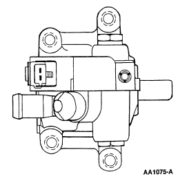
The system consists of an engine-driven pump with an integral solenoid (Figure 46) on the pump that is triggered by the powertrain control module (PCM). Fan speed is controlled by adjusting current to the solenoid, which then changes the fluid flow to the hydraulic motor. More current means the solenoid opens up, allowing higher pressure to increase the fan speed. The fan always turns due to solenoid current leakage, even in cold engine cases. The motor is driven by the pump. It contains a shaft on which the fan mounts. The motor also contains quick connect fittings for the high pressure lines. The cooler is similar to the power steering cooler (same purpose and function, to keep the fluid cool).

For information on the EGR vacuum regulator (EVR) solenoid, refer to the description of the Exhaust Gas Recirculation Systems .
For information on the electric secondary air injection pump, refer to the description of the Secondary Air Injection Systems .
For information on the Evaporative Emission (EVAP) canister purge valve, refer to the description of the Evaporative Emission Systems .
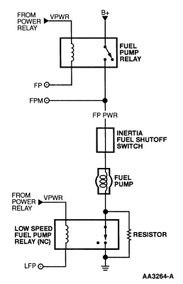
The Fuel Pump (FP) is a PCM output signal that is used to control the electric fuel pump. With the electronic EC power relay contacts closed, vehicle power (VPWR) is sent to the coil of the fuel pump relay. For electric fuel pump operation, the PCM grounds the FP circuit, which is connected to the coil of the fuel pump relay. This energizes the coil and closes the contacts of the relay, sending B+ through the FP PWR circuit to the electric fuel pump. When the ignition key is turned on, the electric fuel pump runs for about one second, but is then turned off by the PCM if engine rotation is not detected.
For applications with two speed fuel pumps, a normally closed low speed fuel pump relay (Figure 47) is wired into the fuel pump ground circuit. With the low speed fuel pump relay contacts in the normally closed position, there is no extra resistance in the ground circuit for high speed operation. For low speed fuel pump operation, the PCM will ground the Low Fuel Pump (LFP) circuit, which opens the relay contacts. With the relay contacts open, the fuel pump ground circuit now passes through a resistor that is wired into the circuit.

Note: For the LS6/LS8, the FPDM functions are incorporated in the Rear Electronic Module (REM). Fuel pump operation is the same as applications using the stand-alone FPDM. The REM will, however, communicate diagnostic information through the BUS +/- circuits (SCP) instead of using a fuel pump monitor (FPM) circuit.
The Fuel Pump (FP) signal is a duty cycle command sent from the powertrain control module (PCM) to the fuel pump driver module (FPDM) (Table 4). The FPDM uses the FP command to operate the fuel pump at the speed requested by the PCM or to turn the pump off.
TABLE 4—FUEL PUMP DUTY CYCLE OUTPUT FROM PCM
| FP Duty Cycle Command | PCM Status | FPDM Actions |
|---|---|---|
| 0-5% | PCM will not output this duty cycle. | Invalid FP duty cycle. FPDM will send 25% duty cycle signal on the fuel pump monitor (FPM) circuit. The fuel pump will be off. |
| 5-51% | Normal operation. | FPDM will operate the fuel pump at the speed requested. ("FP duty cycle" x 2 = pump speed % of full on [for example FP duty cycle = 42%. 42x2=84. Pump is run at 84% of full on.]). FPDM will send 50% duty cycle signal on FPM circuit. |
| 51-67.5% | PCM will not output this duty cycle. | Invalid FP duty cycle. FPDM will send 25% duty cycle signal on the fuel pump monitor (FPM) circuit. The fuel pump will be off. |
| 67.5-82.5% | To request the fuel pump off, the PCM will output a 75% duty cycle. | Valid fuel pump off command from PCM. FPDM will not operate the fuel pump. FPDM will send a 50% duty cycle signal on the FPM circuit. |
| 82.5-100% | PCM will not output this duty cycle. | Invalid FP duty cycle. FPDM will send 25% duty cycle signal on the FPM circuit. The fuel pump will be off. |
NOTE: Also refer to PCM Inputs, Fuel Pump Monitor and Powertrain Control Hardware, Fuel Pump Driver Module.
For information on the fuel injectors, refer to the description of the Fuel Systems .
For information on the fuel pressure regulator control (FPRC) solenoid, refer to the description of the Fuel Systems .
For information on the generator (Gen Com), refer to the description of PCM/Controlled Charging System .
For information on the idle air control solenoid, refer to the description of the Intake Air Systems .
For information on the intake manifold tuning valve, refer to the description of the Intake Air Systems .
For information on the intake manifold runner control, refer to the description of the Intake Air Systems .
For information on the secondary air injection bypass solenoid, refer to the description of the Secondary Air Injection Systems .
For information on the secondary air injection diverter solenoid, refer to the description of the Secondary Air Injection Systems .
For information on the solid state relay, refer to the description of the Secondary Air Injection Systems .
The transmission control indicator lamp (TCIL) is an output signal from the PCM that controls the lamp on/off function depending on the engagement or disengagement of overdrive. Refer to Transmission Control Switch in Hardware PCM Inputs.
The Wide Open Throttle Air Conditioning Cut-off (WAC) output is used by the PCM to disengage the A/C clutch when A/C compressor operation is not desirable. Under normal conditions, with the A/C off, the PCM will ground the WAC output, which opens the normally closed WOT A/C cut-off relay (this relay may be inside the constant control relay module). When the A/C demand switch is turned on, and the A/C cycling switch and A/C high pressure switch high pressure contacts are closed, voltage is supplied to the WOT A/C cut-off relay contacts and to the ACCS circuit. The voltage on the ACCS circuit indicates to the PCM that A/C is requested. The PCM will then verify that A/C clutch operation is desirable (for example, engine not cranking, overheated or not at WOT). If A/C clutch operation is desirable, the PCM will adjust idle speed as necessary and "unground" the WAC output. This closes the normally closed WOT A/C cut-off relay and for all vehicles except Contour/Mystique/Cougar, allows voltage to be supplied to the A/C clutch. For Contour/Mystique/Cougar, when the WOT A/C cut-off relay contacts are closed voltage is supplied to the A/C clutch relay. This will close the normally open contacts of the A/C clutch relay and allow voltage to be supplied to the A/C clutch.
For these applications, the wide open throttle A/C cutoff relay (may be referred to as the A/C relay) is normally open. There is no direct electrical connection between the A/C switch or EATC Module and the A/C clutch. The PCM will receive a signal indicating that A/C is requested (for Town Car and Continental, this message is sent through the BUS + and BUS - circuits). When A/C is requested, the PCM will check other A/C related inputs that are available (such as ACP (SW), ACCS). If these inputs indicate A/C operation is OK, and the engine conditions are OK (such as coolant temperature, engine rpm, throttle position), the PCM will ground the WAC output, closing the relay contacts and sending voltage to the A/C clutch.
For information on the vapor management valve (EVAP canister purge valve), refer to the description of the Evaporative Emission Systems .

