1999 PCED On Board Diagnostics II |
SECTION 1: Description and Operation |
The Evaporative Emission (EVAP) system prevents fuel vapor build-up in the sealed fuel tank. Fuel vapors trapped in the sealed tank are vented through the vapor valve assembly on top of the tank. The vapors leave the valve assembly through a single vapor line and continue to the EVAP canister (located in the engine compartment, in the rear of vehicle near luggage compartment area or along the frame rail) for storage until the vapors are purged to the engine for burning.
There are three types of Evaporative Emission (EVAP) systems:
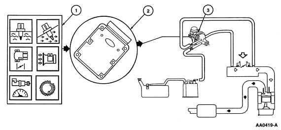
The Vapor Management Flow system consists of a fuel tank, fuel filler cap, fuel vapor vent valve, EVAP canister, EVAP canister purge valve, intake air tube assembly, powertrain control module (PCM) and connecting wires and fuel vapor hoses. This system is being used on flexible fuel vehicles only. Operation of the system is as follows: (Figure 85)

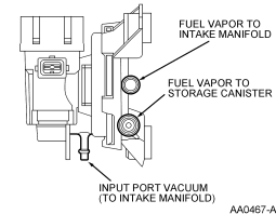
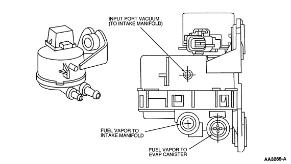
The EVAP canister purge valve (Figure 87) is the part of the vapor management flow and EVAP running loss systems that is controlled by the PCM. This valve controls the flow of vapors (purging) from the EVAP canister to the intake manifold during various engine operating modes. The EVAP canister purge valve is a normally closed valve.
The fuel vapor vent valve assembly (Figure 94) for the Vapor Management Flow system functions in the same manner as in the EVAP Running Loss system.
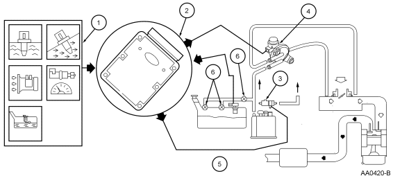
The EVAP Running Loss system (Figure 86) consists of a fuel tank, fuel filler cap, fuel tank mounted or in-line fuel vapor control valve, fuel vapor vent valve, EVAP canister, fuel tank mounted or fuel pump mounted or in-line fuel tank pressure (FTP) sensor, EVAP canister purge valve, intake manifold hose assembly, canister vent (CV) solenoid, powertrain control module (PCM) and connecting wires and fuel vapor hoses.
The EVAP canister purge valve (Figure 87) and (Figure 88) is the part of the EVAP running loss system that is controlled by the PCM. This valve controls the flow of vapors (purging) from the EVAP canister to the intake manifold during various engine operating modes. The EVAP canister purge valve is normally closed valve.
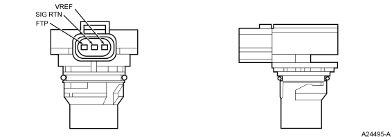
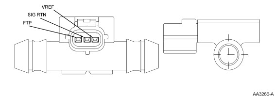
The fuel tank pressure (FTP) sensor (Figure 89) or inline fuel tank pressure (FTP) sensor (Figure 90) is used to measure the fuel tank pressure during the EVAP monitor test on vehicles equipped with the Running Loss-type system. Also, it is used to control excessive fuel tank pressure by forcing the system to purge.
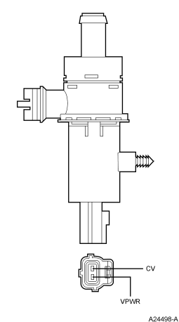
During the EVAP Running Loss System test monitor, the canister vent (CV) solenoid (Figure 91) seals the EVAP canister from atmospheric pressure. This allows the EVAP canister purge valve to obtain the target vacuum in the fuel tank during the monitor run.
The fuel vapor control valve (Figure 92) is in series with the fuel vapor vent valve and the EVAP canister. This valve is referred to as a grade vent valve on some applications. The function of this fuel vapor control valve is to close the flow of liquid fuel to the EVAP canister purge valve or EVAP canister during refueling and to prevent the collection of liquid fuel in the fuel vapor hoses by overfilling the fuel tank.
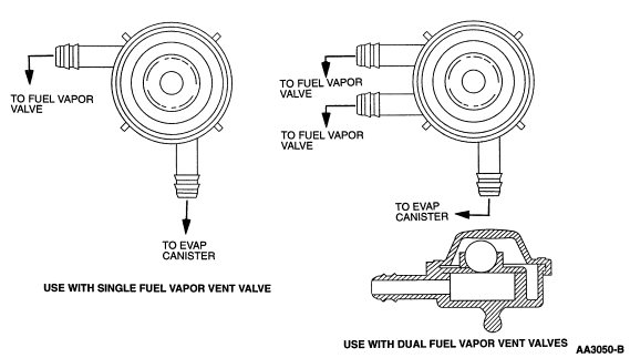
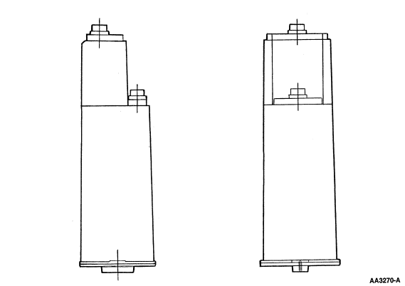
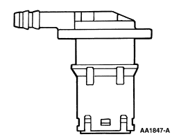
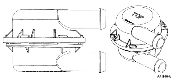
The fuel vapor vent valve assembly that is mounted on the top of the fuel tank is used to control the flow of fuel vapor entering the fuel tank vapor delivery line to the EVAP canister. This valve is referred to as a fill limiting vent valve on some applications. The head valve portion of the assembly prevents the fuel tank from overfilling during refueling operations. The assembly also has a spring supported float which prevents liquid fuel from entering the fuel tank vapor delivery line under any vehicle severe handling or a vehicle rollover condition. In the vertical position, the open bottom float will lift and shut off the orifice. In the rollover position, the spring will push the float closed when the rollover angle permits liquid gasoline to reach the orifice. In the upside down position, the weight of the open bottom float and the spring force will close the orifice. Two types of fuel vapor vent valves are used that can be serviceable. They are: (1) O-ring type (Figure 93) and (2) rubber grommet type (Figure 94). The Escort/Tracer, Contour/Mystique, LS6/LS8, Ranger, Expedition/Navigator and heavy duty F-Series (F250, F350) have fuel vapor vent valves that are an integral part of the plastic fuel tank and cannot be repaired separately.
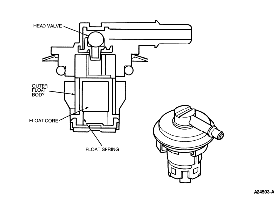
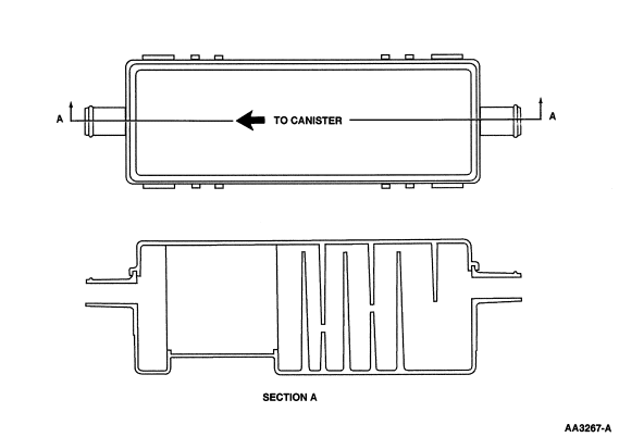
The fuel vapor separator assembly (Figure 95) is used to prevent dust and debris from entering the EVAP canister and canister vent (CV) solenoid from the atmosphere causing partial contamination or complete blockage of the EVAP canister-CV solenoid assembly.
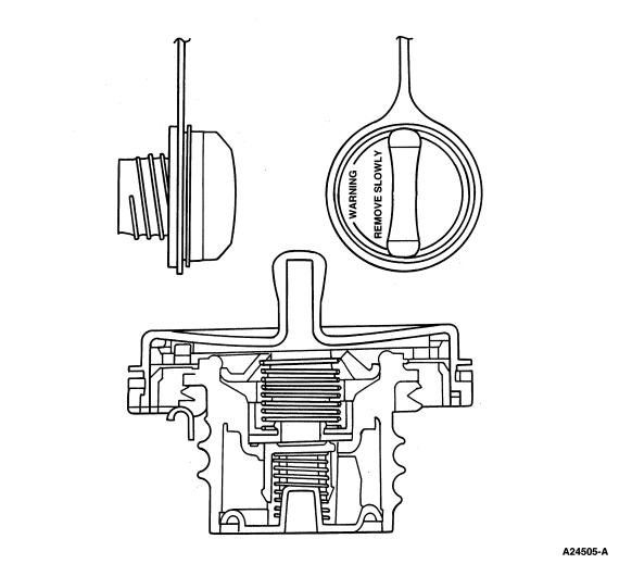
The fuel filler cap (Figure 96) is used to prevent fuel spill and close the evaporative emission/fuel system to atmosphere.
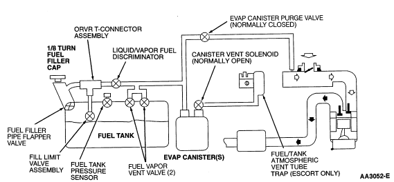
The liquid/vapor fuel discriminator (Figure 97) is a device that separates the liquid and vapor state of fuel at the fuel tank vent and allows only the fuel vapor to move through the EVAP Running Loss system with the liquid fuel remaining in the fuel tank. This is used on Escort/Tracer (2V) and late-year introduction Contour/Mystique.
The basic elements forming the ORVR system (Figure 98) and (Figure 99) and (Figure 100) operation are as follows when fuel is dispensed:
Between refueling events, the EVAP canister is purged with fresh air so that it may be used again to store vapors accumulated engine soaks or subsequent refueling events. The vapors drawn off of the carbon in the EVAP canister are consumed in the engine
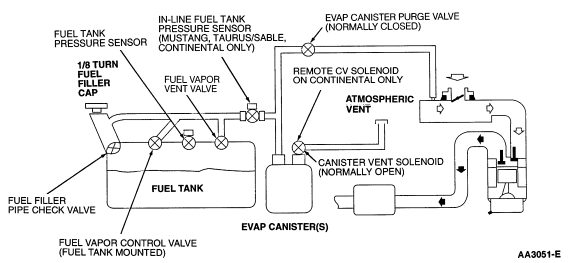
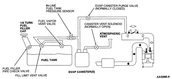
The fuel filler pipe check valve (Figure 101) on ORVR systems for Taurus/Sable (2V), Crown Victoria/Grand Marquis and Town Car is located internal to the fuel filler pipe where the tube joins the fuel tank. The purpose of this check valve is to prevent liquid fuel from re-entering the fuel filler pipe from the fuel tank on refueling.
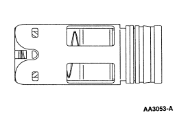
The fill limit valve assembly (Figure 102) on the Escort/Tracer and Contour/Mystique (late-year introduction) provides two functions. These functions are to control fuel tank volume and to prevent fuel from entering the vent tube in a roll-over condition. The fill limit valve assembly is a three piece device consisting of a vent tube, a vapor seal (which has an O-ring on both ends for leak protection) and a check valve which consists of a float with a spring assembly. The vent valve during vehicle driving (in upright position), controls fuel level by a float point based on the fuel density. In a roll-over situation, the spring closes the float and the vapor seal O-rings provide the additional seal to prevent fuel from entering the vent tube.
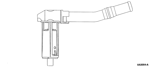
The fill limit vent valve assembly on the LS6/LS8 is welded on the top center of the fuel tank assembly and functions and appears the same as a fuel vapor control valve (Figure 104). It is connected to the EVAP canister by the EVAP canister tube. During refueling the fuel vapor passes through the valve, which by design prevents liquid from passing and is stored in the EVAP canister. It is a single stage shut-off valve. The 1.12 cm (44 inch) and the 0.25 cm (0.10 inch) openings shut off when the fuel height reaches the valve bottom. When the fuel tank is full no vapor passes through the fill limit vent valve. The small opening of 0.10 cm (0.040 inch) the fuel vapor vent valve is the only vent for relieving the pressure in the fuel tank. When the fuel level drops below the valve bottom the fuel tank vents through the opening in the fill limit vent valve as well as the fuel vapor vent valve. There is a pressure relief valve in the fill limit vent valve. It starts opening at 12.44 kPa (50 in-H2O) pressure and is fully open at 19.90 kPa (80 in-H2 0) pressure in the event of a fuel tank excessive pressure condition.
The fuel filler pipe flapper valve (Figure 103) is located internally between bottom of the fuel filler pipe and the fuel tank. The purpose of this valve is to minimize fuel flow from backing up the fuel filler pipe. Also, this valve is not a positive seal to the fuel tank.
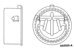
The fuel vapor control valve (fuel tank mounted) (Figure 104) is part of the On-Board Refueling Vapor Recovery (ORVR) system used on the Mustang, Taurus/Sable, Crown Victoria/Grand Marquis, LS6/LS8, Town Car and Continental for preventing liquid fuel from entering the EVAP canister and EVAP canister purge valve.
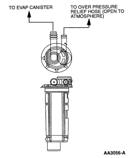
The fuel vapor vent valve (Figure 93) and (Figure 94), dependent of vehicle application), for the ORVR systems functions in the same manner as in the EVAP Running Loss system.
The liquid/vapor fuel discriminator (Figure 97) description for the ORVR system on the Escort/Tracer and Contour/Mystique is located in the EVAP Running Loss system hardware in this section.
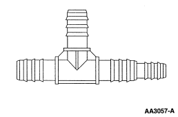
The fuel vapor recovery system primary component on the Escort/Tracer and Contour/Mystique is a fixed orifice and a roll-over check valve contained in a T - connector assembly (Figure 105). The T - connector assembly is located between the liquid/vapor fuel discriminator inlet port (hose) and the fuel tank vent tube path. The orifice recirculates fuel vapor to the fuel filler neck/pipe during the refueling process to displace fresh air (along with vapor) pulled into the fuel filler neck/pipe by the refueling nozzle. The system vapor generation is reduced by replacing the fresh air with the recirculated vapor. The roll-over feature of the T- connector protects against fuel from passing back from the fuel tank through the fuel filler neck/pipe and down the fuel filler recirculation tube during a crash roll-over. This prevents fuel leakage in cases where fuel vapor hoses or EVAP components may be displaced during a high speed crash.
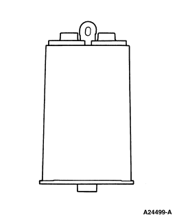
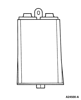
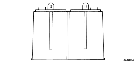
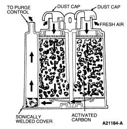
The fuel vapors from the fuel tank are stored in the EVAP canister. When the engine is running above idle, the vapors are purged from the EVAP canister into the engine for combustion. OBD II vehicle EVAP canisters are sometimes used in pairs depending on the size or number of fuel tanks. The OBD II vehicle applications and number of EVAP canisters used are shown in the following table:
EVAPORATIVE EMISSION SYSTEM EVAP CANISTER CONFIGURATIONS
| Vehicle Application | Number of EVAP Canisters | EVAP Canister Volume | Figure Number |
|---|---|---|---|
| LS6/LS8, Continental | 2 | 0.925L and 2.0L | 109 and 108 |
| Explorer/Mountaineer | 2 | 1.0L | 106 |
| Windstar | 2 | 1.0L and 1.5L | 106 and 107 |
| Escort/Tracer | 1 | 1.5L | 107 |
| 4.2L/4.6L/5.4L/6.8L, (F250) | 2 | 1.5L | 107 |
| Contour/Mystique, Mustang, Cougar, Taurus/Sable, Town Car, Crown Victoria/Grand Marquis, Ranger | 1 | 2.0L | 108 |
| Expedition/Navigator, Windstar (late year introduction), Ranger Flexible Fuel, 4.2L/4.6L/5.4L (F150) | 1 | 2.8L | 110 |
| 4.2L/4.6L/5.4L E-Series, 4.2L/5.4L/6.8L (F350 or F700) | 1 or 2 | 2.8L | 110 |
