NI-2 CHECK FOR OPEN LAMP CIRCUIT
- Deactivate system.
- Disconnect air bag diagnostic monitor.
- Turn ignition switch to RUN.
- Is air bag indicator on?
NI-3 CHECK FOR ELECTRONIC INSTRUMENT CLUSTER
- Check for electronic instrument cluster.
- Is the air bag indicator operated by an electronic instrument cluster?
NI-4 CHECK INSTRUMENT CLUSTER
- Remove plastic locking wedge from black air bag diagnostic monitor harness connector.
- Measure voltage between Pins 11(+) and 10(-).
- Is voltage equal to battery voltage?
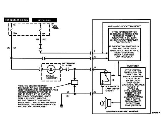
PINPOINT TESTS: CONTINUOUS AIR BAG INDICATOR
Continuous Air Bag Indicator
Diagnostic Trouble Code Timed Out, or Diagnostic Monitor Disconnected or Inoperative, or No Ignition Voltage to Diagnostic Monitor
Normal Operation
The air bag indicator is designed to light for six (± two) seconds when the ignition switch is turned to RUN. This initial six seconds of air bag indicator illumination is considered normal operation and is called "prove-out" of the air bag indicator. If the air bag diagnostic monitor has detected any faults in the air bag system, it will flash the air bag indicator a series of times to indicate the highest priority code stored in memory.
The diagnostic trouble codes are two digits.
- The first digit is displayed by a series of flashes at a rate of one per second. A two second pause follows the first digit.
- The second digit is then displayed by a series of flashes at a rate of one per second. A five second pause follows the second digit.
- The code then repeats, starting with the first digit.
After the code has flashed completely five times, the air bag indicator will light continuously until the ignition switch is cycled. If the air bag indicator comes on when the ignition switch is turned to RUN and immediately stays on for more than eight seconds continuously, then a fault exists in the air bag indicator circuit.
The air bag diagnostic monitor incorporates a solid state circuit which shorts the air bag indicator line (Circuit 608, BK/Y) to ground to turn on the air bag indicator. When the black air bag diagnostic monitor harness connector is unplugged from the air bag diagnostic monitor, a shorting bar within the harness connector shorts Pin 11 (air bag indicator) and Pin 10 (ground) together, causing a continuous lamp. This shorting bar may be removed for servicing purposes by removing the black spacer (locking wedge) in the black air bag diagnostic monitor harness connector.
The air bag diagnostic monitor requires power at Pin 6 to energize the air bag indicator circuit properly. Loss of ignition voltage at Pin 6 due to open circuit or short to ground will result in a continuous air bag indicator due to the ignition voltage applied to Pin 19. An open or short to ground in the lamp circuit at Pin 11 will result in no air bag indicator (see No Air Bag Indicator description).
Possible Causes
Continuous air bag indicator illumination can be caused by:
- A diagnostic trouble code has flashed five times after the ignition switch was turned to RUN (after prove-out) and has timed out. Recycling the ignition switch will redisplay the DTCs.
- A disconnected or poorly connected air bag diagnostic monitor may not push the shorting bar between Pins 10 and 11 into its fully retracted position. This shorts the air bag indicator line to ground and causes the air bag indicator to glow continuously.
- A damaged air bag diagnostic monitor.
- Shorted air bag indicator wiring.
- Loss of ignition voltage at Pin 6 of the air bag diagnostic monitor.
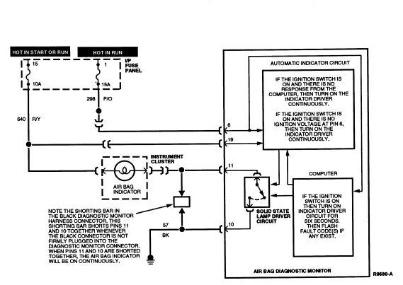
Electrical Schematic Ś Continuous Air Bag Indicator
CI-1 UNDERSTAND FUNCTION
- Read the normal operation description for CONTINUOUS AIR BAG INDICATOR.
- Examine the fault code schematic.
- Is fault code operation well understood?
CI-2 CHECK FOR DIAGNOSTIC TROUBLE CODE TIMED OUT
- Cycle ignition switch to OFF and then to RUN.
- Does a diagnostic trouble code start flashing after a six second (±2) indicator prove-out?
CI-3 CHECK IF DIAGNOSTIC MONITOR IS CONNECTED
- Inspect connectors on air bag diagnostic monitor.
- Are connectors fully pushed together?
CI-4 CHECK FOR IGNITION VOLTAGE
- Deactivate system.
- Disconnect air bag diagnostic monitor.
- Turn ignition switch to RUN.
- Measure voltage between Pins 6 (+) and 18 (-) of the air bag diagnostic monitor harness connector.
- Is voltage measured equal to battery voltage?
CI-5 CHECK FOR SHORTED INDICATOR WIRING
- Remove plastic locking wedge from the black air bag diagnostic monitor harness connector.
- Turn ignition switch to RUN.
- Is air bag indicator on?
CI-6 INSPECT SHORTING BAR
- Inspect shorting bars on plastic locking wedge for proper operation.
- Are shorting bars in good working order?
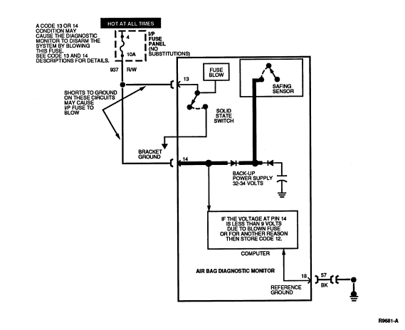
PINPOINT TESTS: DIAGNOSTIC TROUBLE CODE 12
Diagnostic Trouble Code 12 Ś Low Battery Voltage
Normal Operation
The air bag diagnostic monitor measures the voltage at Pin 14 of the air bag diagnostic monitor connector. Voltage at Pin 14 should be equal to battery voltage. If the voltage at Pin 14 drops to less than 9 volts, the air bag diagnostic monitor will store in memory and flash out on the air bag indicator a DTC 12. Should the loss of battery voltage at Pin 14 be intermittent or repaired, the air bag diagnostic monitor will flash out a DTC 52 (or higher priority code if one exists) on the next ignition switch cycle.
Possible Causes
Low voltage at air bag diagnostic monitor Pin 14 can be caused by:
- An open in the battery circuit that would prevent battery
voltage from reaching air bag diagnostic monitor Pin 14.
NOTE: If a short to ground exists on any of the Circuits 607 (LB/O), 614 (GY/O), 615 (GY/W), or 616 (PK/BK) leading to a DTC 13 or 53, or similarly a short to ground exists on any of Circuits 617 (PK/O), 619 (PK/W), 624 (Y/W), 625 (Y/LG) leading to a DTC 14 or 54, the air bag diagnostic monitor will activate a solid state switch at Pin 13 of the air bag diagnostic monitor. This causes the 10 amp battery fuse to blow, thus disarming the air bag system and preventing inadvertent air bag deployment. If the 10 amp instrument panel (or power distribution in some vehicles) battery fuse has blown, it must be replaced by a 10A fuse.
 WARNING: UNDER NO CIRCUMSTANCES SUBSTITUTE ANOTHER FUSE VALUE. ANY FUSE OTHER
THAN 10A MAY CAUSE DISARMING FAILURE AND MAY RESULT IN DANGER TO THE OCCUPANTS
OF THE VEHICLE. DO NOT ATTEMPT TO REPLACE THE 10A FUSE UNLESS THE AIR BAG
SYSTEM FIRST HAS BEEN DEACTIVATED (SEE DEACTIVATION PROCEDURE FOR DETAILS).
WARNING: UNDER NO CIRCUMSTANCES SUBSTITUTE ANOTHER FUSE VALUE. ANY FUSE OTHER
THAN 10A MAY CAUSE DISARMING FAILURE AND MAY RESULT IN DANGER TO THE OCCUPANTS
OF THE VEHICLE. DO NOT ATTEMPT TO REPLACE THE 10A FUSE UNLESS THE AIR BAG
SYSTEM FIRST HAS BEEN DEACTIVATED (SEE DEACTIVATION PROCEDURE FOR DETAILS).
After the air bag diagnostic monitor has disarmed the air bag system, it will not be enabled to disarm again until the appropriate condition (DTC 13, 14, 53, or 54) has been serviced and cleared (see DTC 13, 14, 53, and 54 and Diagnostic Trouble Code Clearing procedure descriptions for further details).
- A short to ground on the battery feed circuit between the fuse and Pin 13 or Pin 14 of the air bag diagnostic monitor.
- A concern in the charging system causing battery voltage to drop below 9 volts.
Electrical Schematic Ś Diagnostic Trouble Code 12
12-1 UNDERSTAND FUNCTION
- Cycle the ignition switch to OFF and then to RUN and confirm that DTC 12 is flashing on the air bag indicator.
- Read the normal operation description for DTC 12.
- Examine the diagnostic trouble code schematic.
- Is the diagnostic trouble code operation well understood?
NOTE: This is a hard fault. The fault condition is still present. This fault may not be cleared until it is serviced and flashes out as a DTC 52.
12-2 CHECK CHARGING SYSTEM
- Measure charging system voltage.
- Is voltage greater than 9 volts?
12-3 CHECK BATTERY FEED
- Deactivate system.
- Disconnect air bag diagnostic monitor.
- Turn ignition switch from OFF to RUN.
- Measure voltage between air bag diagnostic monitor harness connector Pins 14 (+) and 18 (-).
- Is voltage on Pin 14 equal to battery voltage?
12-4 CHECK BATTERY FUSE
- Check 10A battery fuse feeding air bag diagnostic monitor harness connector Pins 14 and 13.
- Check power distribution fuse feeding the 10A fuse.
- Is either fuse blown?
12-5 CHECK FOR SHORT IN HARNESS
- Replace blown fuse. NO SUBSTITUTIONS.
WARNING: CERTAIN FAULT CONDITIONS (DIAGNOSTIC CODE 13/53 OR 14/54) MAY CAUSE THE AIR BAG DIAGNOSTIC MONITOR
TO INTENTIONALLY BLOW THE 10A BATTERY FUSE TO DISARM
THE AIR BAG SYSTEM. DO NOT SUBSTITUTE ANOTHER FUSE VALUE FOR THE 10A BATTERY
FUSE. ANY OTHER FUSE VALUE MAY CAUSE FUTURE DISARMING FAILURE AND MAY RESULT IN
DANGER TO THE OCCUPANTS OF THE VEHICLE. ONCE THE AIR BAG DIAGNOSTIC MONITOR
HAS DISARMED THE SYSTEM, IT WILL NOT ATTEMPT TO DO SO
AGAIN UNTIL THE APPROPRIATE DIAGNOSTIC TROUBLE CODE (13/53 OR 14/54) HAS BEEN
CLEARED. THUS DO NOT REACTIVATE SYSTEM UNTIL ALL DIAGNOSTIC TROUBLE CODES HAVE
BEEN REPAIRED AND CLEARED.
- Does fuse blow again?
12-6 CONFIRM CONDITION
- Reconnect air bag diagnostic monitor.
- Does fuse blow again?
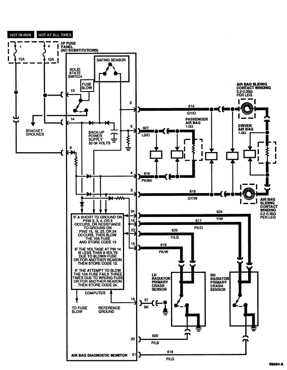
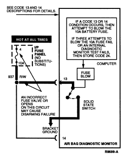
PINPOINT TESTS: DIAGNOSTIC TROUBLE CODE 13
Diagnostic Trouble Code 13 Ś Air Bag Circuit Shorted to Ground
Normal Operation
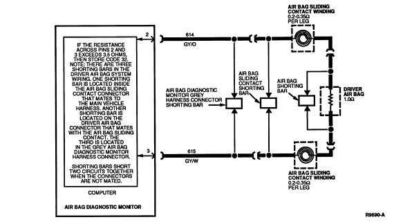
The air bag diagnostic monitor measures the voltage at Pins 2, 3, 4, and 5 of the air bag diagnostic monitor connector. The voltage at these pins is set by the air bag diagnostic monitor and varies with charging system voltage (the expected voltages are shown in the chart below). If the air bag diagnostic monitor detects low voltage on any of these pins, the air bag diagnostic monitor will store in memory and flash out on the air bag indicator a DTC 13 to indicate a possible short to ground on these circuits.
At the same time the air bag diagnostic monitor begins flashing out DTC 13, it attempts to disarm the air bag system to prevent inadvertent deployment of the air bag(s) by blowing the 10A battery fuse feeding air bag diagnostic monitor Pins 13 and 14. It attempts to blow the fuse by activating a solid state switch which shorts the battery feed at Pin 13 to sheet metal ground at the air bag diagnostic monitor's bracket.
The air bag diagnostic monitor will make up to three attempts to blow this fuse, spaced at one minute apart.
- If the air bag diagnostic monitor has blown the fuse and thus removed battery voltage at Pin 14, a DTC 12 will be stored (see DTC 12 and 52 description for further details).
- If the air bag diagnostic monitor attempts to blow the 10A battery fuse three times and fails each time, a DTC 24 will be stored (see DTC 24 and64 description for further details).
- After the 10A fuse is blown or three attempts to blow it fail, the air bag diagnostic monitor will not attempt to disarm again until the DTC 13 condition has been serviced and cleared (See Diagnostic Trouble Code Clearing procedure description for further details).
- Should the short on Pins 2, 3, or 5 be intermittent or repaired, the air bag diagnostic monitor will flash out a DTC 53 (or a higher priority DTC such as DTC 12 if one exists) on the next ignition switch cycle.
| Pin | 9.0 | 9.5 | 10.0 | 10.5 | 11.0 | 11.5 | 12.0 |
|---|---|---|---|---|---|---|---|
| 2 | 1.5 | 1.6 | 1.7 | 1.8 | 1.9 | 2.0 | 2.1 |
| 3 | 1.5 | 1.6 | 1.7 | 1.8 | 1.9 | 2.0 | 2.1 |
| 4 | 1.5 | 1.6 | 1.7 | 1.8 | 1.9 | 2.0 | 2.1 |
| 5 | 1.5 | 1.6 | 1.7 | 1.8 | 1.9 | 2.0 | 2.1 |
| Pin | 12.5 | 13.0 | 13.5 | 14.0 | 14.5 | 15.0 | 15.5 | 16.0 |
|---|---|---|---|---|---|---|---|---|
| 2 | 2.2 | 2.3 | 2.4 | 2.5 | 2.6 | 2.7 | 2.8 | 2.9 |
| 3 | 2.2 | 2.3 | 2.4 | 2.5 | 2.6 | 2.7 | 2.8 | 2.9 |
| 4 | 2.2 | 2.3 | 2.4 | 2.5 | 2.6 | 2.7 | 2.8 | 2.9 |
| 5 | 2.2 | 2.3 | 2.4 | 2.5 | 2.6 | 2.7 | 2.8 | 2.9 |
Possible Causes
Low voltage at air bag diagnostic monitor Pins 2, 3, 4, or 5 can be caused by:
- A short to ground on Circuits 607 (LB/O), 614 (GY/O), 615 (GY/W), or 616 (PK/BK) causing the diagnostic voltage to drop.
- Resistance to ground on Circuits 617 (PK/O), 619 (PK/W), 624 (Y/W), 625 (Y/LG) or internal resistance to ground in either of the radiator primary crash sensors may activate an air bag diagnostic monitor circuit which may cause the voltage to drop.
- An internal short to ground within the air bag sliding contact causing the driver side air bag circuit(s) to be shorted to ground.
- An internal short to case ground within the driver side air bag module or passenger side air bag module .
WARNING: SERVICING A DTC 13 WILL USUALLY OCCUR AFTER SERVICING OF A DTC 12 HAS
BEEN COMPLETED. UNDER NO CIRCUMSTANCES SUBSTITUTE ANOTHER FUSE VALUE FOR THE
10A BATTERY FUSE. ANY FUSE OTHER THAN 10A MAY CAUSE DISARMING FAILURE AND MAY
RESULT IN DANGER TO THE OCCUPANTS OF THE VEHICLE. DO NOT ATTEMPT TO REPLACE THE
10A BATTERY FUSE UNLESS THE AIR BAG SYSTEM FIRST HAS BEEN DEACTIVATED (SEE
DEACTIVATION PROCEDURE FOR DETAILS).
Electrical Schematic Ś Diagnostic Trouble Code 13
13-1 UNDERSTAND FUNCTION
- Cycle the ignition switch to OFF and then to RUN and confirm that DTC 13 is flashing on the air bag indicator.
- Read the normal operation description for DTC 13.
- Examine the diagnostic trouble code schematic.
- Is the diagnostic trouble code operation well understood?
NOTE: This is a hard fault. The fault condition may not be cleared until it is serviced and flashes out as a DTC 53. Under normal circumstances a DTC 12 will have just been serviced.
13-2 CHECK FOR SHORTED AIR BAG(S)
- Deactivate system. Carefully disconnect air bags during deactivation.
- Turn ignition switch from OFF to RUN.
- Is DTC 13 still flashing?
13-3 CHECK DRIVER CIRCUIT FOR SHORTS
- Disconnect air bag diagnostic monitor.
- Examine wiring and connector where air bag sliding contact mates to main vehicle harness underneath steering column.
- Check for pinched and/or chafed wires.
- Measure resistance between air bag diagnostic monitor harness connector Pin 2 (Circuit 614, GY/O) and Pin 18 (Circuit 57, BK).
- Is Pin 2 shorted to ground?
13-4 CHECK PASSENGER CIRCUIT FOR SHORTS
- Measure resistance between air bag diagnostic monitor harness connector Pin 5 (Circuit 607, GY/O) and Pin 18 (Circuit 57, BK).
- Is Pin 5 shorted to ground?
13-5 CHECK PRIMARY SENSORS
- Measure resistance between air bag diagnostic monitor harness connector Pin 15 (Circuit 619, PK/W) and Pin 18 (Circuit 57, BK).
- Measure resistance between air bag diagnostic monitor harness connector Pin 16 (Circuit 617, PK/O) and Pin 18 (Circuit 57, BK).
- Are resistance readings infinite (open)?
13-6 DETERMINE IF SENSOR OR WIRE IS SHORTED
- Disconnect radiator primary crash sensor corresponding to the circuit with resistance to ground found in Step 13-5.
- Measure resistance across normally open contacts of radiator primary crash sensor at the sensor connector.
- Is resistance reading infinite (open)?
13-7 DETERMINE WHICH BAG IS SHORTED
- Make sure that shorting bar is properly installed in passenger side air
bag connector.
WARNING: USE A HAND-HELD DIGITAL OHMMETER WITH LESS THAN 10MA SHORT-CIRCUIT
CURRENT ON THE LOWEST RESISTANCE SCALE POSSIBLE (TYPICALLY 200 OHMS SETTING).
FAILURE TO USE A METER OF THIS TYPE MAY CAUSE PERSONAL INJURY DUE TO AIR BAG
DEPLOYMENT.
- Measure resistance between either of the terminals in the passenger side air bag connector and the metal case of the passenger side air bag module .
- Is resistance reading infinite (open)?
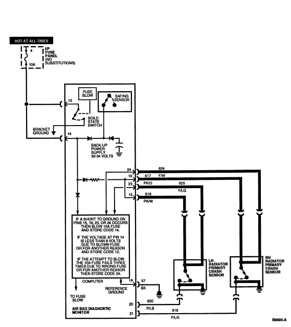
PINPOINT TESTS: DIAGNOSTIC TROUBLE CODE 14
Diagnostic Trouble Code 14 Ś Primary Crash Sensor Circuit Shorted to Ground
Normal Operation
The air bag diagnostic monitor measures the voltage at Pins 23 and 24 of the air bag diagnostic monitor connector. The voltage at these pins varies with charging system voltage (the expected voltages are shown in the chart below). If the air bag diagnostic monitor measures a voltage of less than 5 volts on either of these pins, the air bag diagnostic monitor will store in memory and flash out on the air bag indicator a DTC 14 to indicate a possible short to ground on these circuits.
At the same time the air bag diagnostic monitor begins flashing out DTC 14, it attempts to disarm the air bag system to prevent inadvertent deployment of the air bag(s) by blowing the 10A battery fuse feeding air bag diagnostic monitor's bracket.
The air bag diagnostic monitor will make up to three attempts to blow this fuse, spaced at one minute apart.
- If the air bag diagnostic monitor has blown the fuse and thus removed battery voltage at Pin 14, a DTC 12 will be stored (see DTC 12 and 52 description for further details).
- If the air bag diagnostic monitor attempts to blow the 10A battery fuse three times and fails each time, a DTC 24 will be stored (see DTC 24 and 64 description for further details).
- After the 10A fuse is blown or three attempts to blow it fail, the air bag diagnostic monitor will not attempt to disarm again until the DTC 13 condition has been serviced and cleared (see Diagnostic Trouble Code Clearing procedure description for further details).
- Should the short on Pins 23 or 24 be intermittent or repaired, the air bag diagnostic monitor will flash out a DTC 54 (or a higher priority DTC such as DTC 12 if one exists) on the next ignition switch cycle.
| Pin | 9.0 | 9.5 | 10.0 | 10.5 | 11.0 | 11.5 | 12.0 |
|---|---|---|---|---|---|---|---|
| 23 | 8.6 | 9.1 | 9.6 | 10.1 | 10.6 | 11.1 | 11.6 |
| 24 | 8.6 | 9.1 | 9.6 | 10.1 | 10.6 | 11.1 | 11.6 |
| Pin | 12.5 | 13.0 | 13.5 | 14.0 | 14.5 | 15.0 | 15.5 | 16.0 |
|---|---|---|---|---|---|---|---|---|
| 23 | 12.1 | 12.6 | 13.1 | 13.6 | 14.1 | 14.6 | 15.1 | 15.6 |
| 24 | 12.1 | 12.6 | 13.1 | 13.6 | 14.1 | 14.6 | 15.1 | 15.6 |
Possible Causes
Low voltage at diagnostic monitor Pins 2, 3, 4, or 5 can be caused by:
- A short to ground on Circuits 617 (PK/O), 619 (PK/W), 624 (Y/W), or 625 (Y/LG) causing the diagnostic voltage to drop.
- An internal short to case ground within either of the radiator
primary crash sensors.
WARNING: SERVICING A DTC 14 WILL USUALLY OCCUR AFTER SERVICING OF A DTC 12 HAS
BEEN COMPLETED. UNDER NO CIRCUMSTANCES SUBSTITUTE ANOTHER FUSE VALUE FOR THE
10A BATTERY FUSE. ANY FUSE OTHER THAN 10A MAY CAUSE DISARMING FAILURE AND MAY
RESULT IN DANGER TO THE OCCUPANTS OF THE VEHICLE. DO NOT ATTEMPT TO REPLACE THE
10A BATTERY FUSE UNLESS THE AIR BAG SYSTEM FIRST HAS BEEN DEACTIVATED (SEE
DEACTIVATION PROCEDURE FOR DETAILS).
Electrical Schematic Ś Diagnostic Trouble Code 14
14-1 UNDERSTAND FUNCTION
- Cycle the ignition switch to OFF and then to RUN and confirm that DTC 14 is flashing on the air bag indicator.
- Read the normal operation description for DTC 14.
- Examine the diagnostic trouble code schematic.
- Is the diagnostic trouble code operation well understood?
NOTE: This is a hard fault. The fault condition may not be cleared until it is serviced and flashes out as a DTC 54. Under normal circumstances a DTC 12 will have just been serviced.
14-2 DETERMINE WHICH CIRCUIT IS SHORTED
- Deactivate system.
- Disconnect air bag diagnostic monitor.
- Set ohmmeter to 200,000 ohm scale or AUTO.
- Measure resistance between Pin 18 (Circuit 57, BK) of the air bag
diagnostic monitor harness connector and all of the following:
- Pin 15 (Circuit 619, PK/W)
- Pin 16 (Circuit 617, PK/O)
- Pin 23 (Circuit 625, Y/LG)
- Pin 24 (Circuit 624, Y/W)
- Are all the resistance readings infinite (open)?
14-3 DETERMINE IF SENSOR OR WIRE IS SHORTED
- Disconnect primary crash sensor corresponding to the shorted circuit found in Step 14-2.
- Measure resistance across normally open contacts of primary crash sensor at the sensor connector.
- Is resistance reading infinite (open)?
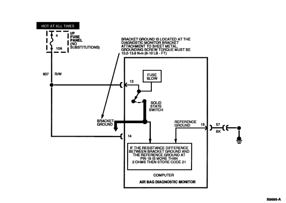
PINPOINT TESTS: DIAGNOSTIC TROUBLE CODE 21
Diagnostic Trouble Code 21 Ś Diagnostic Monitor Not Mounted to Vehicle Properly
Normal Operation
The air bag diagnostic monitor measures the resistance between the ground connection at its bracket and the reference ground at Pin 18. If the air bag diagnostic monitor measures a difference of more than 2.0 ohms between the ground at Pin 18 and the ground at its bracket, the air bag diagnostic monitor will store in memory and flash out a DTC 21 on the air bag indicator. Should the difference in resistance between Pins 18 and air bag diagnostic monitor bracket ground be serviced or otherwise reduced to less than 2.0 ohms, the air bag diagnostic monitor will flash out a DTC 61 (or a higher priority DTC if one exists) on the next ignition switch cycle.
Possible Causes
High resistance at the air bag diagnostic monitor bracket ground can be caused by:
- A poor attachment of the air bag diagnostic monitor due to loose mounting, dirt, or corrosion at the air bag diagnostic monitor bracket mounting surface(s).
Electrical Schematic Ś Diagnostic Trouble Code 21
21-1 UNDERSTAND FUNCTION
- Cycle the ignition switch to OFF and then to RUN and confirm that DTC 21 is flashing on the air bag indicator.
- Read the normal operation description for DTC 21.
- Examine the diagnostic trouble code schematic.
- Is the diagnostic trouble code operation well understood?
NOTE: This is a hard fault. The fault condition is still present. This fault may not be cleared until it is serviced and flashes out as a DTC 61.
21-2 MEASURE RESISTANCE
- Deactivate system.
- Disconnect air bag diagnostic monitor.
- Disconnect negative battery cable.
- Set ohmmeter to lowest scale (200 ohms or AUTO).
- "Zero" ohmmeter by touching leads together and record resistance reading.
- Measure resistance between air bag diagnostic monitor bracket and a nearby good sheet metal ground. Subtract the reading found when zeroing ohmmeter.
- Is the resistance greater than 2 ohms?
21-3 RECHECK RESISTANCE
- Measure resistance between air bag diagnostic monitor bracket and a nearby good sheet metal ground. Subtract the reading found when zeroing ohmmeter.
- Is the resistance greater than 2 ohms?
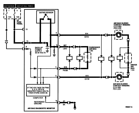
PINPOINT TESTS: DIAGNOSTIC TROUBLE CODE 22
Diagnostic Trouble Code 22 Ś Safing Sensor Output Circuit Shorted to Battery Voltage
Normal Operation
The air bag diagnostic monitor measures the voltage at Pins 2, 3, 4, and
5 of the air bag diagnostic monitor connector. The voltage at these pins is set
by the air bag diagnostic monitor and varies with charging system voltage (the
expected voltages are shown in the chart below). If the air bag diagnostic
monitor measures a voltage of more than 5 volts on any of these pins, the air
bag diagnostic monitor will store in memory and flash out on the air bag
indicator a DTC 22. Should the unexpected high voltage on Pins 2, 3, 4, or 5 be
repaired or intermittent, the diagnostic monitor will flash out a DTC 62 (or a
higher priority DTC if one exists) on the next ignition switch cycle.
| Pin | 9.0 | 9.5 | 10.0 | 10.5 | 11.0 | 11.5 | 12.0 |
|---|---|---|---|---|---|---|---|
| 2 | 1.5 | 1.6 | 1.7 | 1.8 | 1.9 | 2.0 | 2.1 |
| 3 | 1.5 | 1.6 | 1.7 | 1.8 | 1.9 | 2.0 | 2.1 |
| 4 | 1.5 | 1.6 | 1.7 | 1.8 | 1.9 | 2.0 | 2.1 |
| 5 | 1.5 | 1.6 | 1.7 | 1.8 | 1.9 | 2.0 | 2.1 |
| Pin | 12.5 | 13.0 | 13.5 | 14.0 | 14.5 | 15.0 | 15.5 | 16.0 |
|---|---|---|---|---|---|---|---|---|
| 2 | 2.2 | 2.3 | 2.4 | 2.5 | 2.6 | 2.7 | 2.8 | 2.9 |
| 3 | 2.2 | 2.3 | 2.4 | 2.5 | 2.6 | 2.7 | 2.8 | 2.9 |
| 4 | 2.2 | 2.3 | 2.4 | 2.5 | 2.6 | 2.7 | 2.8 | 2.9 |
| 5 | 2.2 | 2.3 | 2.4 | 2.5 | 2.6 | 2.7 | 2.8 | 2.9 |
Possible Causes
High voltage at air bag diagnostic monitor Pins 2, 3, 4, or 5 caused by:
- A short to battery or ignition on Circuits 607 (LB/O), 614 (GY/O), 615 (GY/W), or 616 (PK/BK) causing the diagnostic voltage to rise.
- A short in the air bag sliding contact between Circuits 614 and some of the horn or speed control wiring.
- An internal air bag diagnostic monitor failure such as a short across the normally open contacts of the safing sensor.
Electrical Schematic Ś Diagnostic Trouble Code 22
22-1 UNDERSTAND FUNCTION
- Cycle the ignition switch to OFF and then to RUN and confirm that DTC 22 is flashing on the air bag indicator.
- Read the normal operation description for DTC 22.
- Examine the diagnostic trouble code schematic.
- Is the diagnostic trouble code operation well understood?
NOTE: This is a hard fault. The fault condition is still present. This fault may not be cleared until it is serviced and flashes out as a DTC 62.
22-2 MEASURE DRIVER SIDE VOLTAGE
- Deactivate system. Inspect driver side air bag harness wires for potential shorts to speed control or horn wiring.
- Disconnect air bag diagnostic monitor.
- Turn ignition switch to RUN.
- Measure voltage between air bag diagnostic monitor harness connector Pins 2 (Circuit 614, GY/O) and 18 (Circuit 57, BK).
- Is voltage measured greater than zero?
22-3 MEASURE PASSENGER SIDE VOLTAGE
- Measure voltage between air bag diagnostic monitor harness connector Pins 5 (Circuit 607, LB/O) and 18 (Circuit 57, BK).
- Is voltage measured greater than zero?
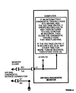
PINPOINT TESTS: DIAGNOSTIC TROUBLE CODE 23
Diagnostic Trouble Code 23 Ś Memory Clear Circuit Improperly Grounded
Normal Operation
The air bag diagnostic monitor records air bag system diagnostic trouble codes in its non-volatile memory (NVM). Upon servicing and correction of the faults, the diagnostic trouble codes may be cleared from the air bag diagnostic monitor's NVM. Under normal circumstances, the air bag diagnostic monitor expects an open circuit on Pin 17 of the air bag diagnostic monitor.
During Diagnostic Trouble Code Clearing (see Diagnostic Trouble Code Clearing procedure for details), the circuit on Pin 17 will be temporarily shorted to ground.
- If this clearing procedure is performed improperly, or if Pin 17 is improperly shorted to ground in another fashion, the air bag diagnostic monitor will store in memory and flash out on the air bag indicator a DTC 23.
- Should the short on Pin 17 to ground be repaired or intermittent, the air bag diagnostic monitor will flash out a DTC 63 (or a higher priority DTC if one exists) on the next ignition switch cycle.
Possible Causes
Improper grounding of the Memory Clear circuit can be caused by:
- A short to ground on Circuit 631 (T/R) can cause improper Memory Clear grounding.
- Improper Diagnostic Trouble Code Clearing procedure performance can cause improper Memory Clear grounding (see Diagnostic Trouble Code Clearing procedure for details).
Electrical Schematic Ś Diagnostic Trouble Code 23
23-1 UNDERSTAND FUNCTION
- Cycle the ignition switch to OFF and then to RUN and confirm that DTC 23 is flashing on the air bag indicator.
- Read the normal operation description for DTC 23.
- Examine the diagnostic trouble code schematic.
- Is the diagnostic trouble code operation well understood?
NOTE: This is a hard fault. The fault condition is still present. This fault may not be cleared until it is serviced and flashes out as a DTC 63.
23-2 MEASURE RESISTANCE
- Deactivate system.
- Disconnect air bag diagnostic monitor.
- Set ohmmeter to 200,000 scale or AUTO.
- Measure resistance between air bag diagnostic monitor harness connector Pins 17 (Circuit 631, T/R) and 18 (Circuit 57, BK).
- Is resistance reading infinite (open)?
PINPOINT TESTS: DIAGNOSTIC TROUBLE CODE 24
Diagnostic Trouble Code 24 Ś System Disarm Failure or Internal Diagnostic Monitor Fault
Normal Operation
The air bag diagnostic monitor measures the voltage at Pins 2, 3, 5, 6, 23 and 24 of the air bag diagnostic monitor connector.
- If the air bag diagnostic monitor measures low voltage on Pins 2, 3, 4, or 5 (or a voltage of less than 5 volts on Pins 23 or 24), the air bag diagnostic monitor will flash out a DTC 13 (or 14) on the air bag indicator to indicate a possible short to ground on these circuits (see DTC 13 and 53 or DTC 14 and 54 description for details).
- At the same time the air bag diagnostic monitor begins flashing out the DTC 13 or 14, it attempts to disarm the air bag system to prevent inadvertent deployment of the air bag(s) by blowing the 10A battery fuse feeding diagnostic monitor Pins 13 and 14. It attempts to blow the fuse by activating a solid state switch which shorts the battery feed at Pin 13 to sheet metal ground at the air bag diagnostic monitor's bracket.
WARNING: UNDER NO CIRCUMSTANCES SHOULD ANOTHER FUSE VALUE BE SUBSTITUTED FOR
THE 10A BATTERY FUSE. ANY FUSE OTHER THAN 10A MAY CAUSE DISARMING FAILURE AND
MAY RESULT IN DANGER TO THE OCCUPANTS OF THE VEHICLE. DO NOT ATTEMPT TO REPLACE
THE 10A BATTERY FUSE UNLESS THE AIR BAG SYSTEM FIRST HAS BEEN DEACTIVATED (SEE
DEACTIVATION PROCEDURE FOR DETAILS).
The air bag diagnostic monitor will make up to three attempts to blow this fuse, spaced at one minute apart.
- If the air bag diagnostic monitor has blown the fuse and thus removed battery voltage at Pin 14, a DTC 12 will be stored (see DTC 12 and 52 descriptions for further details).
- If the air bag diagnostic monitor attempts to blow the 10A battery fuse three times and fails each time, a DTC 24 will be stored.
- After the 10A fuse is blown or three attempts to blow it fail, the air bag diagnostic monitor will not attempt to disarm again until the DTC 13 or 14 condition has been serviced and cleared (see Diagnostic Trouble Code Clearing description for further details).
- If a DTC 24 is stored in this manner, due to a system disarm failure, the next ignition switch cycle will produce a DTC 64 (or a higher priority DTC if one exists).
The air bag diagnostic monitor also performs several self-tests every time the ignition switch is turned to RUN.
- If any of these tests fail, the air bag diagnostic monitor will flash DTC 24.
- If any of these conditions later resumes normal operation, the next ignition switch cycle will produce a DTC 64 (or a higher priority DTC if one exists).
Possible Causes
System disarm failure or internal diagnostic failure can be caused by:
- An improper fuse value in the battery circuit feeding air bag
diagnostic monitor Pins 13 and 14.
WARNING: THE BATTERY FUSE MUST BE REPLACED WITH A 10A FUSE. UNDER NO
CIRCUMSTANCES SUBSTITUTE ANOTHER FUSE VALUE FOR THE 10A BATTERY FUSE. ANY FUSE
OTHER THAN 10A MAY CAUSE DISARMING FAILURE AND MAY RESULT IN DANGER TO THE
OCCUPANTS OF THE VEHICLE. DO NOT ATTEMPT TO REPLACE THE 10A BATTERY FUSE UNLESS
THE AIR BAG SYSTEM FIRST HAS BEEN DEACTIVATED (SEE DEACTIVATION PROCEDURE FOR
DETAILS).
- Excessive resistance or opens in the battery feed circuit due to corrosion, poor crimps, etc. The excess resistance could occur in the wiring at the air bag diagnostic monitor harness Pin 13, the 10A battery fuse terminal, or elsewhere in the battery feed circuit.
- A vehicle charging system concern could prevent the air bag diagnostic monitor from drawing enough current to perform its disarm.
- An internal air bag diagnostic monitor failure on self-test or system disarm.
Electrical Schematic Ś Diagnostic Trouble Code 24
24-1 UNDERSTAND FUNCTION
- Cycle the ignition switch to OFF and then to RUN and confirm that DTC 24 is flashing on the air bag indicator.
- Read the normal operation description for DTC 24.
- Examine the diagnostic trouble code schematic.
- Is the diagnostic trouble code operation well understood?
NOTE: This is a hard fault. The fault condition is still present. This fault may not be cleared until it is serviced and flashes out as a DTC 64.
24-2 CONFIRM BATTERY CONNECTION
- Deactivate system.
- Disconnect air bag diagnostic monitor.
- Measure voltage between air bag diagnostic monitor harness connector Pins 13 (+) (HOT AT ALL TIMES) and 18 (-) (Circuit 57, BK).
- Is voltage measured equal to charging system voltage?
24-3 CHECK FUSE
- Inspect HOT AT ALL TIMES fuse feeding air bag diagnostic monitor Pins 13 and 14.
- Is fuse value correct (10A)? WARNING: CERTAIN FAULT CONDITIONS (SEE DIAGNOSTIC TROUBLE CODE 13/53 OR 14/54)
MAY CAUSE THE DIAGNOSTIC MONITOR TO INTENTIONALLY BLOW THE 10A BATTERY FUSE TO
DISARM THE AIR BAG SYSTEM. DO NOT SUBSTITUTE ANOTHER FUSE VALUE FOR THE 10A
BATTERY FUSE. ANY OTHER FUSE VALUE MAY CAUSE FUTURE DISARMING FAILURE AND MAY
RESULT IN DANGER TO THE OCCUPANTS OF THE VEHICLE. ONCE THE DIAGNOSTIC MONITOR
HAS DISARMED THE SYSTEM, IT WILL NOT ATTEMPT TO DO SO AGAIN UNTIL THE
APPROPRIATE DIAGNOSTIC TROUBLE CODE (13/53 OR 14/54) HAS BEEN CLEARED. THUS DO
NOT REACTIVATE SYSTEM UNTIL ALL DIAGNOSTIC TROUBLE CODES HAVE BEEN REPAIRED AND
CLEARED.
24-4 CHECK FOR SHORT TO BATTERY
- Remove 10A HOT AT ALL TIMES fuse feeding air bag diagnostic monitor Pins 13 and 14.
- Measure voltage between air bag diagnostic monitor harness connector Pins 13 (+) (HOT AT ALL TIMES) and 18 (-) (Circuit 57, BK).
- Is voltage reading zero?
24-5 CHECK FOR INCORRECT WIRING
- Examine air bag diagnostic monitor harness connector Pin 22. Pin 22 should not be connected.
- Is a wire connected at Pin 22?
PINPOINT TESTS: DIAGNOSTIC TROUBLE CODE 32
Diagnostic Trouble Code 32 Ś Driver Side Air Bag Circuit High Resistance or Open
Normal Operation
While the ignition switch is in the RUN position, the air bag diagnostic monitor runs periodic checks on the resistance of the driver and passenger air bag circuits.
- Normal resistance from Pin 2 (Driver Air Bag Feed) to Pin 3 (Driver Air Bag Return) is between 1.4 ohms and 2.0 ohms. This resistance total results from the sum of the components in the circuit: the air bag (approximately 1 ohm) and the air bag sliding contact (0.20 ohm to 0.35 ohm per winding, 2 windings total) plus a small amount of resistance due to the wire itself, crimps, etc.
- If the resistance across these two pins exceeds 3.5 ohms, the air bag diagnostic monitor will interpret this as high resistance and the air bag diagnostic monitor will store in memory and flash out on the air bag indicator a DTC 32.
- If the high resistance is later serviced or otherwise falls into the normal range, the next ignition switch cycle will produce a DTC 72 (or a higher priority DTC if one exists).
NOTE: The air bag connector, air bag diagnostic monitor harness connector, and the air bag sliding contact connector have metal spring clips that act as shorting bars. These shorting bars are built into the plastic hardshell connectors. The shorting bars are designed to short Circuits 614 (GY/O) and 615 (GY/W) together when the connectors are not mated. DO NOT attempt to remove the air bag shorting bar and measure the resistance of the air bag.
The air bag sliding contact shorting bar may be removed to measure the air bag sliding contact resistance. Likewise, the shorting bar(s) in the air bag diagnostic monitor harness connector may be removed by removing the black spacer (locking wedge) from the connector. Use extreme caution when reinstalling the shorting bars to ensure they are installed correctly.
Possible Causes
Excessive resistance across Pins 2 and 3 can be caused by:
- A poor connection or corrosion where the air bag sliding contact connects into the main wiring harness. The air bag sliding contact connector at the base of the steering column may have excessive resistance between the male and female terminals in the connector. Also, corrosion may occur on the terminal crimps on both the air bag sliding contact terminals and the main wiring harness terminals.
- An open circuit or high resistance in the air bag sliding contact windings inside the air bag sliding contact.
- An open circuit or high resistance in the wiring harness in either Circuit 614 (GY/O) or Circuit 615 (GY/W).
- An open circuit or high resistance in the driver side air bag module . DO NOT attempt a direct resistance measurement of the air bag. Follow the diagnostic procedure to determine if the air bag resistance is higher than normal.
Electrical Schematic Ś Diagnostic Trouble Code 32
32-1 UNDERSTAND FUNCTIONS
- Cycle the ignition switch to OFF and then to RUN and confirm that DTC 32 is flashing on the air bag indicator.
- Read the normal operation description for DTC 32.
- Examine the diagnostic trouble code schematic.
- Is the diagnostic trouble code operation well understood?
NOTE: This is a hard fault. The fault condition is still present. This fault may not be cleared until it is serviced and flashes out as a DTC 72.
32-2 MEASURE RESISTANCE
- Disconnect air bag diagnostic monitor.
- Deactivate system.
- Set ohmmeter to lowest scale (200 ohms or AUTO).
- "Zero" ohmmeter by touching leads together and record resistance reading.
- Remove plastic locking wedge from gray harness connector.
- Measure resistance between air bag diagnostic monitor harness connector Pins 2 (Circuit 614, GY/O) and 3 (Circuit 615, GY/W). Subtract the reading found when zeroing ohmmeter.
- Is result less than 3.0 ohms?
32-3 CHECK FOR DTC 32
- Reconnect air bag diagnostic monitor.
- Turn ignition switch from OFF to RUN.
- Is DTC 32 still flashing?
32-4 ISOLATE RESISTANCE
- Disconnect air bag sliding contact at base of steering column.
- Install air bag simulator on main wiring harness at base of steering column.
- Measure resistance between air bag diagnostic monitor harness connector Pins 2 (Circuit 614, GY/O) and 3 (Circuit 615, GY/W). Subtract the reading found when zeroing ohmmeter.
- Is result equal to 2 ohm ± 0.2 ohm?
32-5 CHECK FOR DTC 32 AGAIN
- Reactivate system.
- Cycle ignition switch to OFF then RUN.
- is diagnostic trouble code 32 flashing?
PINPOINT TESTS: DIAGNOSTIC TROUBLE CODE 33
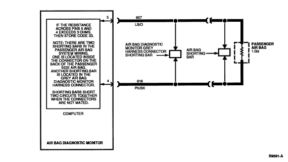
Diagnostic Trouble Code 33 Ś Passenger Side Air Bag Circuit High Resistance or Open
Normal Operation
While the ignition switch is in the RUN position, the air bag diagnostic monitor runs periodic checks on the resistance of the driver and passenger air bag circuits.
- Normal resistance from Pin 5 (Passenger Air Bag Feed) to Pin 4 (Passenger Air Bag Return) is between 0.9 ohm and 1.2 ohms. This resistance consists of the passenger air bag resistance (approximately 1.0 ohm) plus a small amount of resistance due to the wire itself, crimps, etc.
- If the resistance across Pin 5 and 4 exceeds 3 ohms, the air bag diagnostic monitor will store in memory and flash out on the air bag indicator a DTC 33.
- If the high resistance is later serviced or otherwise falls into the normal range, the next ignition switch cycle will produce a DTC 73 (or a higher priority DTC if one exists).
NOTE: The air bag connector and the air bag diagnostic monitor harness connector have metal spring clips that act as shorting bars. These shorting bars are built into the plastic hardshell connectors. The shorting bars are designed to short Circuit 607 (LB/O) and 616 (PK/B) together when the connectors are not mated. DO NOT attempt to remove the air bag shorting bar and measure the resistance of the air bag.
The shorting bar(s) in the air bag diagnostic monitor harness connector may be removed by removing the black spacer (locking wedge) from the connector. Use extreme caution when reinstalling the spacers to ensure they are installed correctly.
Possible Causes
Excessive resistance across Pins 2 and 3 can be caused by:
- An open circuit or high resistance in the wiring harness in either Circuit 607 (LB/O) or Circuit 616 (PK/BK).
- An open circuit or high resistance in the passenger side air bag module . DO NOT attempt a direct resistance measurement of the air bag. Follow the diagnostic procedure to determine if the air bag resistance is higher than normal.
Electrical Schematic Ś Diagnostic Trouble Code 33
33-1 UNDERSTAND FUNCTION
- Cycle the ignition switch to OFF and then to RUN and confirm that DTC 33 is flashing on the air bag indicator.
- Read the normal operation description for DTC 33.
- Examine the diagnostic trouble code schematic.
- Is the diagnostic trouble code operation well understood?
NOTE: This is a hard fault. The fault condition is still present. This fault may not be cleared until it is serviced and flashes out as a DTC 73.
33-2 MEASURE RESISTANCE
- Deactivate system.
- Disconnect air bag diagnostic monitor.
- Set ohmmeter to lowest scale (200 ohms to AUTO).
- "Zero" ohmmeter by touching leads together and record resistance reading.
- Remove plastic locking wedge from gray harness connector.
- Measure resistance between air bag diagnostic monitor harness connector Pins 5 (Circuit 607, LB/O) and 4 (Circuit 616, PK/BK). Subtract the reading found when zeroing ohmmeter.
- Is result less than 3.0 ohms?
33-3 CHECK FOR DTC 33
- Reconnect air bag diagnostic monitor.
- Turn ignition switch from OFF to RUN.
- Is Diagnostic Trouble Code 33 still flashing?
33-4 CHECK FOR DTC 33 AGAIN
- Reactivate system.
- Cycle ignition switch to OFF then RUN.
- Is DTC 33 flashing?
PINPOINT TESTS: DIAGNOSTIC TROUBLE CODE 34
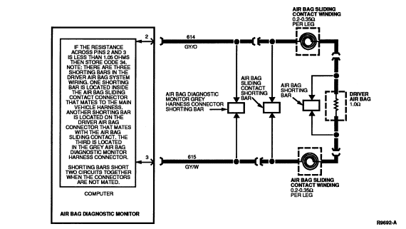
Diagnostic Trouble Code 34 Ś Driver Side Air Bag Circuit Low Resistance or Shorted
Normal Operation
While the ignition switch is in the RUN position, the air bag diagnostic monitor runs periodic checks on the resistance of the driver and passenger air bag circuits. Normal resistance from Pin 2 (Driver Air Bag Feed) to Pin 3 (Driver Air Bag Return) is between 1.4 ohms and 2.0 ohms.
- This resistance total results from the sum of the components in the circuit: the air bag (approximately 1 ohm) and the air bag sliding contact (0.20 ohm to 0.35 ohm per winding, 2 windings total) plus a small amount of resistance due to the wire itself, crimps, etc.
- If the resistance across these two pins is less than 1 ohm, the air bag diagnostic monitor will interpret this as a low resistance and the air bag diagnostic monitor will store in memory and flash out on the air bag indicator a DTC 34.
- If the low resistance is later serviced or otherwise rises into the normal range, the next ignition switch cycle will produce a DTC 74 (or a higher priority DTC if one exists).
NOTE: The air bag connector, air bag diagnostic monitor harness connector, and the air bag sliding contact connector have metal spring clips that act as shorting bars. These shorting bars are built into the plastic hardshell connectors. The shorting bars are designed to short Circuit 614 (GY/O) and 615 (GY/W) together when the connectors are not mated. DO NOT attempt to remove the air bag shorting bar and measure the resistance of the air bag.
The air bag sliding contact shorting bar may be removed to measure the air bag sliding contact resistance. Likewise, the shorting bar(s) in the air bag diagnostic monitor harness connector may be removed by removing the black spacer (locking wedge) from the connector. Use extreme caution when reinstalling the shorting bars to ensure they are installed correctly.
Possible Causes
Low resistance across Pins 2 and 3 can be caused by:
- A poorly mated air bag connector, air bag diagnostic monitor harness connector, or air bag sliding contact connector may not push the shorting bars back into their fully retracted position.
- A damaged or worn shorting bar may short Circuits 614 (GY/O) and 615 (GY/W).
- A short in the air bag sliding contact windings or harness wires between Circuits 614 (GY/O) and 615 (GY/W).
- A short circuit or low resistance in the driver side air bag module . DO NOT attempt a direct resistance measurement of the air bag. Follow the diagnostic procedure to determine if the air bag resistance is higher than normal.
Electrical Schematic Ś Diagnostic Trouble Code 34
34-1 UNDERSTAND FUNCTION
- Cycle the ignition switch to OFF and then to RUN and confirm that DTC 34 is flashing on the air bag indicator.
- Read the normal operation description for DTC 34.
- Examine the diagnostic trouble code schematic.
- Is the diagnostic trouble code operation well understood?
NOTE: This is a hard fault. The fault condition is still present. This fault may not be cleared until it is serviced and flashes out as a DTC 74.
34-2 MEASURE RESISTANCE
- Deactivate system. Leave driver side air bag harness connector empty (DO NOT install air bag simulator).
- Disconnect air bag diagnostic monitor.
- Remove plastic locking wedge from gray harness connector.
- Measure resistance between air bag diagnostic monitor harness connector Pins 2 (Circuit 614, GY/O) and 3 (Circuit 615, GY/W).
- Is the resistance reading infinite (open)?
NOTE: Try turning steering wheel while making the measurement.
34-3 VERIFY CONDITION
- Install air bag simulator onto air bag sliding contact connector at steering wheel .
- Reconnect air bag diagnostic monitor.
- Turn ignition switch from OFF to RUN.
- Is DTC 34 flashing?
NOTE: Examine air bag sliding contact to main harness connector for an example of a normal shorting bar.
34-4 CHECK FOR HARNESS SHORT
- Disconnect air bag sliding contact at base of steering column where it mates with vehicle harness.
- Measure resistance between air bag diagnostic monitor harness connector Pins 2 (Circuit 614, GY/O) and 3 (Circuit 615, GY/W).
- Is the resistance reading infinite (open)?
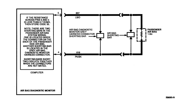
PINPOINT TESTS: DIAGNOSTIC TROUBLE CODE 35
Diagnostic Trouble Code 35 Ś Passenger Side Air Bag Circuit Low Resistance or Shorted
Normal Operation
While the ignition switch is in the RUN position, the air bag diagnostic monitor runs periodic checks on the resistance of the driver and passenger air bag circuits.
- Normal resistance from Pin 5 (Passenger Air Bag Feed) to Pin 4 (Passenger Air Bag Return) is 0.9 ohm and 1.2 ohms.
- This resistance consists of the passenger air bag resistance (approximately 1.0 ohm) plus a small amount of resistance due to the wire itself, crimps, etc.
- If the resistance across Pins 5 and 4 is less than 0.7 ohm, the air bag diagnostic monitor will interpret this as a low resistance and the air bag diagnostic monitor will store in memory and flash out on the air bag indicator a DTC 35.
- If the low resistance is later serviced or otherwise rises into the
normal range, the next ignition switch cycle will produce a DTC 75 (or a higher
priority DTC if one exists).
NOTE: The air bag connector and the air bag diagnostic monitor harness connector have metal spring clips that act as shorting bars. These shorting bars are built into the plastic hardshell connectors. The shorting bars are designed to short Circuits 607 (LB/O) and 616 (PK/BK) together when the connectors are not mated. DO NOT attempt to remove the air bag shorting bar and measure the resistance of the air bag.
The shorting bar(s) in the air bag diagnostic monitor harness connector may be removed by removing the black spacer (locking wedge) from the connector. Use extreme caution when reinstalling the spacers to ensure they are installed co rrectly.
Possible Causes
Low resistance across Pins 5 and 4 can be caused by:
- A poorly mated air bag connector or air bag diagnostic monitor harness connector may not push the shorting bars back into their fully retracted position.
- A damaged or worn shorting bar may short Circuit 607 (LB/O) and 616 (PK/BK).
- A short in the harness wires between Circuits 607 (LB/O) and 616 (PK/BK).
- A short circuit or low resistance in the passenger side air bag module. DO NOT attempt a direct resistance measurement of the air bag. Follow the diagnostic procedure to determine if the air bag resistance is higher than normal.
Electrical Schematic Ś Diagnostic Trouble Code 35
35-1 UNDERSTAND FUNCTION
- Cycle the ignition switch to OFF and then to RUN and confirm that DTC 35 is flashing on the air bag indicator.
- Read the normal operation description for DTC 35.
- Examine the diagnostic trouble code schematic.
- Is the diagnostic trouble code operation well understood?
NOTE: This is a hard fault. The fault condition is still present. This fault may not be cleared until it is serviced and flashes out as a DTC 75.
35-2 MEASURE RESISTANCE
- Deactivate system. Leave passenger side air bag harness connector empty (DO NOT install air bag simulator).
- Disconnect air bag diagnostic monitor.
- Remove plastic locking wedge from gray harness connector.
- Measure resistance between diagnostic monitor harness connector Pins 5 (Circuit 607, LB/O) and 4 (Circuit 616, PK/BK).
- Is the resistance reading infinite (open)?
35-3 CHECK FOR DTC 35
- Install air bag simulator onto passenger side air bag harness connector.
- Reconnect air bag diagnostic monitor.
- Turn ignition switch from OFF to RUN.
- Is DTC 35 flashing?
NOTE: Examine air bag sliding contact to main harness connector for an example of a normal shorting bar.
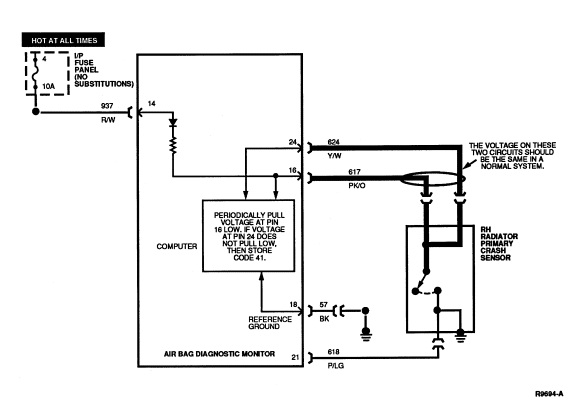
PINPOINT TESTS: DIAGNOSTIC TROUBLE CODE 41
Diagnostic Trouble Code 41 Ś Right Radiator Primary Crash Feed/Return Circuit Open
Normal Operation
The voltage at Pin 16 and Circuit 617 (PK/O) is set by the air bag diagnostic monitor to be slightly less than battery voltage. Circuit 617 is connected to Circuit 624 (Y/W) inside RH radiator primary crash sensor. Therefore, the voltage at Circuit 624 and air bag diagnostic monitor Pin 24 should be the same as the voltage at air bag diagnostic monitor Pin 16.
The air bag diagnostic monitor periodically pulls the voltage at Pin 16 low to verify the connection to Pin 24. If the voltage at Pin 24 does not pull low as a result of this test, the air bag diagnostic monitor will store in memory and flash out on the air bag indicator a DTC 41. If the connection between Pins 16 and 24 is later serviced, the next ignition switch cycle will produce a DTC 81 (or a higher priority DTC if one exists).
Possible Causes
Failure to get low voltage at Pin 24 during the test can be caused by:
- An open circuit in the wiring harness in either Circuit 617 (PK/O) or Circuit 624 (Y/W).
- An open circuit inside RH radiator primary crash sensor across Circuit 617 (PK/O) or Circuit 624 (Y/W).
- A short to battery or ignition voltage in any of the Circuits 617 (PK/O), 619 (PK/W), 624 (Y/W), 625 (Y/LG).
Electrical Schematic Ś Diagnostic Trouble Code 41
41-1 UNDERSTAND FUNCTION
- Cycle the ignition switch to OFF and then to RUN and confirm that DTC 41 is flashing on the air bag indicator.
- Read the normal operation description for DTC 41.
- Examine the diagnostic trouble code schematic.
- Is the diagnostic trouble code operation well understood?
NOTE: This is a hard fault. The fault condition is still present. This fault may not be cleared until it is serviced and flashes out as a DTC 81.
41-2 MEASURE RESISTANCE
- Deactivate system.
- Disconnect air bag diagnostic monitor.
- Set ohmmeter to 200 ohm scale or AUTO.
- "Zero" ohmmeter by touching leads together and record resistance reading.
- Measure resistance between air bag diagnostic monitor harness connector Pins 16 (Circuit 617, PK/O) and 24 (Circuit 624, Y/W). Subtract the reading found when zeroing ohmmeter.
- Is the result less than 2 ohms?
41-3 CHECK FOR SHORTS TO BATTERY
- With air bag diagnostic monitor disconnected, cycle ignition switch to RUN.
- Measure the voltage between the following air bag diagnostic monitor
harness pins and ground:
- Pin 15 (619, PK/W)
- Pin 16 (617, PK/O)
- Pin 23 (625, Y/LG)
- Pin 24 (624, Y/W)
- Is the voltage greater than zero on any of these wires?
41-4 MEASURE RESISTANCE IN SENSOR CONNECTOR
- Locate RH radiator primary crash front air bag sensor and bracket .
- Disconnect RH radiator primary crash sensor from harness.
- Measure resistance between PK/O and Y/W wires in sensor connector.
- Is the resistance reading less than 2 ohms?
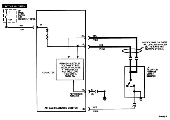
PINPOINT TESTS: DIAGNOSTIC TROUBLE CODE 42
Diagnostic Trouble Code 42 Ś Left Radiator Primary Crash Sensor Feed/Return Circuit Open
Normal Operation
The voltage at Pin 15 and Circuit 619 (PK/W) is set by the air bag diagnostic monitor to be slightly less than battery voltage. Circuit 619 is connected to Circuit 625 (Y/LG) inside LH radiator primary crash sensor. Therefore, the voltage at Circuit 625 and air bag diagnostic monitor Pin 23 should be the same as the voltage at air bag diagnostic monitor Pin 15.
The air bag diagnostic monitor periodically pulls the voltage at Pin 15 low to verify the connection to Pin 23. If the voltage at Pin 24 does not pull low as a result of this test, air bag diagnostic monitor will store in memory and flash out on the air bag indicator a DTC 42. If the connection between Pins 15 and 23 is later serviced, the next ignition switch cycle will produce a DTC 82 (or a higher priority DTC if one exists).
Possible Causes
Failure to get low voltage at Pin 23 during the test can be caused by:
- An open circuit in the wiring harness in either Circuit 619 (PK/W) or Circuit 625 (Y/LG).
- An open circuit inside left radiator primary crash sensor across Circuit 619 (PK/W) or Circuit 625 (Y/LG).
- A short to battery or ignition voltage in any of the Circuits 617 (PK/O), 619 (PK/W), 624 (Y/W), 625 (Y/LG).
Electrical Schematic Ś Diagnostic Trouble Code 42
42-1 UNDERSTAND FUNCTION
- Cycle the ignition switch to OFF and then to RUN and confirm that DTC 42 is flashing on the air bag indicator.
- Read the normal operation description for DTC 42.
- Examine the diagnostic trouble code schematic.
- Is the diagnostic trouble code operation well understood?
NOTE: This is a hard fault. The fault condition is still present. This fault may not be cleared until it is serviced and flashes out as a DTC 82.
42-2 MEASURE RESISTANCE
- Deactivate system.
- Disconnect air bag diagnostic monitor.
- Set ohmmeter to 200 ohm scale or AUTO.
- "Zero" ohmmeter by touching leads together and record resistance reading.
- Measure resistance between air bag diagnostic monitor harness connector Pins 15 (Circuit 619, PK/W) and 23 (Circuit 625, Y/LG). Subtract the reading found when zeroing ohmmeter.
- Is the result less than 2 ohms?
42-3 MEASURE RESISTANCE IN SENSOR CONNECTOR
- Locate LH radiator primary crash front air bag sensor and bracket .
- Measure resistance between PK/W and Y/LG wires in sensor connector.
- Is the resistance reading less than 2 ohms?
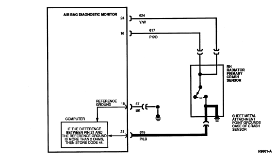
PINPOINT TESTS: DIAGNOSTIC TROUBLE CODE 44
Diagnostic Trouble Code 44 Ś Right Radiator Primary Crash Sensor Not Mounted to Vehicle Properly
Normal Operation
The air bag diagnostic monitor measures the resistance between Pin 21 and the reference ground at Pin 18. If the air bag diagnostic monitor measures a difference of more than 2.0 ohms between the ground at Pin 18 and the ground at Pin 21, the air bag diagnostic monitor will store in memory and flash out on the air bag indicator a DTC 44. Should the difference in resistance between Pin 18 and Pin 21 be serviced or otherwise reduced to less than 2.0 ohms, the air bag diagnostic monitor will flash out a DTC 84 (or a higher priority DTC if one exists) on the next ignition switch cycle.
NOTE: Circuit 618 (P/LG) is riveted to the side of the RH radiator primary crash sensor case and the case of the sensor is grounded to the vehicle at its mounting point.
Possible Causes
High resistance on Pin 21 to ground can be caused by:
- A poor attachment of RH radiator primary crash front air bag sensor and bracket due to loose mounting, dirt, or corrosion at its mounting location.
- An open or damaged wire in Circuit 618 (P/LG).
- An open wire or loose rivet inside RH radiator primary crash front air bag sensor and bracket .
Electrical Schematic Ś Diagnostic Trouble Code 44
44-1 UNDERSTAND FUNCTION
- Cycle the ignition switch to OFF and then to RUN and confirm that DTC 44 is flashing on the air bag indicator.
- Read the normal operation description for DTC 44.
- Examine the diagnostic trouble code schematic.
- Is the diagnostic trouble code operation well understood?
NOTE: This is a hard fault. The fault condition is still present. This fault may not be cleared until it is serviced and flashes out as a DTC 84.
44-2 MEASURE RESISTANCE
- Deactivate system.
- Disconnect air bag diagnostic monitor.
- Disconnect negative battery cable.
- Set ohmmeter to 200 ohm scale or AUTO.
- "Zero" ohmmeter by touching leads together and record resistance reading.
- Measure resistance between air bag diagnostic monitor harness connector Pins 18 (Circuit 57, BK) and 21 (Circuit 618, P/LG). Subtract the reading found when zeroing ohmmeter.
- Is the result greater than 2 ohms?
44-3 CHECK CRASH SENSOR GROUND
- Locate RH radiator primary crash front air bag sensor and bracket .
- Disconnect RH radiator primary crash sensor from harness.
- Measure resistance between P/LG wire in sensor connector and a good, nearby chassis ground. Subtract the reading found when zeroing ohmmeter.
- Is the result less than 2 ohms?
44-4 MEASURE RESISTANCE
- Measure resistance between P/LG wire in RH radiator primary crash sensor connector and a good, nearby chassis ground. Subtract the reading found when zeroing ohmmeter.
- Is the result less than 2 ohms?
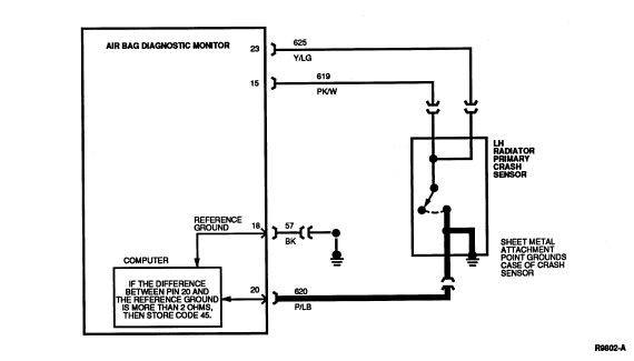
PINPOINT TESTS: DIAGNOSTIC TROUBLE CODE 45
Diagnostic Trouble Code 45 Ś Left Radiator Primary Crash Sensor Not Mounted to Vehicle Properly
Normal Operation
The air bag diagnostic monitor measures the resistance between Pin 20 and the reference ground at Pin 18. If the air bag diagnostic monitor measures a difference of more than 2.0 ohms between the ground at Pin 18 and the ground at Pin 20, the air bag diagnostic monitor will store in memory and flash out on the air bag indicator a DTC 45. Should the difference in resistance between Pin 18 and Pin 20 be serviced or otherwise reduced to less than 2.0 ohms, the air bag diagnostic monitor will flash out a DTC 85 (or a higher priority DTC if one exists) on the next ignition switch cycle.
NOTE: Circuit 620 (P/LB) is riveted to the side of the LH radiator primary crash sensor case and the case of the sensor is grounded to the vehicle at its mounting point.
Possible Causes
High resistance on Pin 20 to ground can be caused by:
- A poor attachment of LH radiator primary crash front air bag sensor and bracket due to loose mounting, dirt, or corrosion at its mounting location.
- An open or damaged wire in Circuit 620 (P/LB).
- An open wire or loose rivet inside LH radiator primary crash front air bag sensor and bracket .
Electrical Schematic Ś Diagnostic Trouble Code 45
45-1 UNDERSTAND FUNCTION
- Cycle the ignition switch to OFF and then to RUN and confirm that DTC 45 is flashing on the air bag indicator.
- Read the normal operation description for DTC 45.
- Examine the diagnostic trouble code schematic.
- Is the diagnostic trouble code operation well understood?
NOTE: This is a hard fault. The fault condition is still present. This fault may not be cleared until it is serviced and flashes out as a DTC 85.
45-2 MEASURE RESISTANCE
- Deactivate system.
- Disconnect air bag diagnostic monitor.
- Disconnect negative battery cable.
- Set ohmmeter to 200 OHM scale or AUTO.
- "Zero" ohmmeter by touching leads together and record resistance reading.
- Measure resistance between air bag diagnostic monitor harness connector Pins 18 (Circuit 57, BK) and 20 (Circuit 620, P/LB). Subtract the reading found when zeroing ohmmeter.
- Is the result greater than 2 ohms?
45-3 CHECK CRASH SENSOR GROUND
- Locate LH radiator primary crash front air bag sensor and bracket .
- Disconnect LH radiator primary crash front air bag sensor and bracket from harness.
- Measure resistance between P/LB wire in sensor connector and a good, nearby chassis ground. Subtract the reading found when zeroing ohmmeter.
- Is the result less than 2 ohms?
45-4 MEASURE RESISTANCE
- Measure resistance between P/LB wire in LH radiator primary crash sensor connector and a good, nearby chassis ground. Subtract the reading found when zeroing ohmmeter.
- Is the result less than 2 ohms?
PINPOINT TESTS: DIAGNOSTIC TROUBLE CODE 52
Diagnostic Trouble Code 52 Ś Intermittent or Repaired Low Battery Voltage
Normal Operation
Refer to Diagnostic Trouble Code 12.
Electrical Schematic Ś Diagnostic Trouble Code 52
Refer to Diagnostic Trouble Code 12.
52-1 UNDERSTAND FUNCTION
- Cycle the ignition switch to OFF and then to RUN and confirm that DTC 12 is flashing on the air bag indicator.
- Read the normal operation description for DTC 12. Read the pinpoint test for DTC 12 as a reference.
- Examine the diagnostic trouble code schematic. Look for areas where intermittent faults may occur.
- Is the diagnostic trouble code operation well understood?
NOTE: This is an intermittent or repaired fault. The fault condition is no longer present.
52-2 CHECK IF REPAIRED
- Deactivate system.
- Has a DTC 12 just been serviced and repaired?
52-3 CLEAR AND CHECK FOR OTHER DTCS
- Check battery fuse feeding air bag diagnostic monitor Pins 13 and 14. Fuse should be 10A, NO SUBSTITUTIONS.
- Clear DTC 52 (see Diagnostic Trouble Code Clearing procedure).
- Does another diagnostic trouble code start flashing?
52-4 CHECK CHARGING SYSTEM
- Examine charging system.
- Has a charging system concern been reported or noticed on the vehicle?
NOTE: An intermittent charging system or battery concern could lead to a DTC 52.
52-5 CHECK BATTERY FEED
- Visually inspect all crimps, terminals, fuses, wires, etc. in the
battery circuit feeding Pins 13 and 14 of the air bag diagnostic monitor. Look
for poor connections, pinched wires, etc.
NOTE: An intermittent open in the battery circuit could lead to a DTC 52.
- Are any concerns noticed?
PINPOINT TESTS: DIAGNOSTIC TROUBLE CODE 53
Diagnostic Trouble Code 53 Ś Intermittent or Repaired Air Bag Circuit Shorted to Ground
Normal Operation
Refer to Diagnostic Trouble Code 13.
Electrical Schematic Ś Diagnostic Trouble Code 53
Refer to Diagnostic Trouble Code 13.
53-1 UNDERSTAND FUNCTION
- Cycle the ignition switch to OFF and then to RUN and confirm that DTC 13 is flashing on the air bag indicator.
- Read the normal operation description for DTC 13. Read the pinpoint tests for DTC 13 as a reference.
- Examine the diagnostic trouble code schematic. Look for areas where intermittent faults may occur.
- Is the diagnostic trouble code operation well understood?
NOTE: This is an intermittent or repaired fault. The fault condition is no longer present.
53-2 CHECK IF REPAIRED
- Deactivate system.
- Has a DTC 13 just been serviced and repaired?
53-3 CLEAR AND CHECK FOR OTHER DTCS
- Check battery fuse feeding diagnostic monitor Pins 13 and 14. Fuse should be 10A, NO SUBSTITUTIONS.
- Clear DTC 53 (see Diagnostic Trouble Code Clearing procedure).
- Does another diagnostic trouble code start flashing?
53-4 CHECK FOR INTERMITTENT SHORTS
- Visually inspect the wiring in the following circuits:
- 614 (GY/O)
- 607 (LB/O)
- 615 (GY/W)
- 616 (PK/BK)
- Look for pinched or chafed wires.
NOTE: An intermittent short to ground on the above wires could lead to a DTC 53.
- Are any concerns noticed?
53-5 CHECK AIR BAG SLIDING CONTACT
- Visually inspect air bag sliding contact wiring at harness connector.
- Visually inspect wiring in steering wheel hub where air bag sliding contact mates to driver air bag connector.
- Visually inspect wiring where passenger air bag mates to harness
connector.
NOTE: An intermittent short to ground on the above wires could lead to a DTC 53.
- Are any concerns noticed?
53-6 CHECK PRIMARY SENSORS
- Visually inspect primary crash sensors and associated circuits:
- 617 (PK/O)
- 619 (PK/W)
- 624 (Y/W)
- 625 (Y/LG)
Look for signs of corrosion of resistance to ground.
NOTE: Intermittent resistance to ground in the above wires or corrosion in a primary sensor could lead to a DTC 53.
- Are any concerns noticed?
PINPOINT TESTS: DIAGNOSTIC TROUBLE CODE 54
Diagnostic Trouble Code 54 Ś Intermittent or Repaired Primary Crash Sensor Circuit Shorted to Ground
Normal Operation
Refer to Diagnostic Trouble Code 14.
Electrical Schematic Ś Diagnostic Trouble Code 54
Refer to Diagnostic Trouble Code 14.
54-1 UNDERSTAND FUNCTION
- Cycle the ignition switch to OFF and then to RUN and confirm that DTC 54 is flashing on the air bag indicator.
- Read the normal operation description for DTC 14. Read the pinpoint tests for DTC 14 as a reference.
- Examine the diagnostic trouble code schematic. Look for areas where intermittent faults may occur.
- Is the diagnostic trouble code operation well understood?
NOTE: This is an intermittent or repaired fault. The fault condition is no longer present.
54-2 CHECK IF REPAIRED
- Deactivate system.
- Has a DTC 14 just been serviced and repaired?
54-3 CLEAR AND CHECK FOR OTHER DTCS
- Check battery fuse feeding diagnostic monitor Pins 13 and 14. Fuse should be 10A, NO SUBSTITUTIONS.
- Clear DTC 54 (see Diagnostic Trouble Code Clearing procedure).
- Does another diagnostic trouble code start flashing?
54-4 CHECK PRIMARY SENSORS
- Visually inspect primary crash sensors and associated circuits:
- 617 (PK/O)
- 619 (PK/W)
- 624 (Y/W)
- 625 (Y/LG)
Look for signs of corrosion of resistance to ground.
NOTE: Intermittent resistance to ground in the above wires or corrosion in a primary sensor could lead to a DTC 54.
- Are any concerns noticed?
PINPOINT TESTS: DIAGNOSTIC TROUBLE CODE 61
Diagnostic Trouble Code 61 Ś Intermittent or Repaired Diagnostic Monitor Not Mounted to Vehicle Properly
Normal Operation
Refer to Diagnostic Trouble Code 21.
Electrical Schematic Ś Diagnostic Trouble Code 61
Refer to Diagnostic Trouble Code 21.
61-1 UNDERSTAND FUNCTION
- Cycle the ignition switch to OFF and then to RUN and confirm that DTC 61 is flashing on the air bag indicator.
- Read the normal operation description for DTC 21. Read the pinpoint tests for DTC 21 as a reference.
- Examine the diagnostic trouble code schematic. Look for areas where intermittent faults may occur.
- Is the diagnostic trouble code operation well understood?
NOTE: This is an intermittent or repaired fault. The fault condition is no longer present.
61-2 CHECK IF REPAIRED
- Deactivate system.
- Has a DTC 21 just been serviced and repaired?
61-3 CLEAR AND CHECK FOR OTHER DTCS
- Clear DTC 61 (see Diagnostic Trouble Code Clearing procedure).
- Does another diagnostic trouble code start flashing?
61-4 CHECK FOR CORROSION
- Visually inspect air bag diagnostic monitor bracket and mounting
surfaces. Look for signs of corrosion or poor contact.
NOTE: High resistance in the air bag diagnostic monitor mount can lead to a DTC 61.
- Is significant corrosion found?
PINPOINT TESTS: DIAGNOSTIC TROUBLE CODE 62
Diagnostic Trouble Code 62 Ś Intermittent or Repaired Safing Sensor Output Circuit Shorted to Battery Voltage
Normal Operation
Refer to Diagnostic Trouble Code 22.
Electrical Schematic Ś Diagnostic Trouble Code 62
Refer to Diagnostic Trouble Code 22.
62-1 UNDERSTAND FUNCTION
- Cycle the ignition switch to OFF and then to RUN and confirm that DTC 62 is flashing on the air bag indicator.
- Read the normal operation description for DTC 22. Read the pinpoint tests for DTC 22 as a reference.
- Examine the diagnostic trouble code schematic. Look for areas where intermittent faults may occur.
- Is the diagnostic trouble code operation well understood?
NOTE: This is an intermittent or repaired fault. The fault condition is no longer present.
62-2 CHECK IF REPAIRED
- Deactivate system.
- Has a DTC 22 just been serviced and repaired?
62-3 CLEAR AND CHECK FOR OTHER DTCS
- Clear DTC 62 (see Diagnostic Trouble Code Clearing procedure).
- Does another diagnostic trouble code start flashing?
62-4 CHECK FOR STEERING COLUMN SHORTS
- Visually inspect driver side air bag harness wires for potential shorts
to speed control or horn wiring.
NOTE: An intermittent short to battery voltage on the air bag harness wires could lead to a Diagnostic Trouble Code 62.
- Are any concerns noticed?
62-5 CHECK FOR INTERMITTENT WIRE SHORTS
- Visually inspect the wires on the following circuits:
- 614 (GY/O)
- 607 (LB/O)
- 615 (GY/W)
- 616 (PK/BK)
Look for potential wire-to-wire shorts.
NOTE: An intermittent short to battery voltage on the above circuits could lead to a DTC 62.
- Are any concerns noticed?
PINPOINT TESTS: DIAGNOSTIC TROUBLE CODE 63
Diagnostic Trouble Code 63 Ś Intermittent or Repaired Memory Clear Circuit Improperly Grounded
Normal Operation
Refer to Diagnostic Trouble Code 23.
Electrical Schematic Ś Diagnostic Trouble Code 63
Refer to Diagnostic Trouble Code 23.
63-1 UNDERSTAND FUNCTION
- Cycle the ignition switch to OFF and then to RUN and confirm that DTC 23 is flashing on the air bag indicator.
- Read the normal operation description for DTC 23. Read the pinpoint tests for DTC 23 as a reference.
- Examine the diagnostic trouble code schematic. Look for areas where intermittent faults may occur.
- Is the diagnostic trouble code operation well understood?
NOTE: This is an intermittent or repaired fault. The fault condition is no longer present.
63-2 CHECK IF REPAIRED
- Deactivate system.
- Has a DTC 23 just been serviced and repaired?
63-3 CLEAR AND CHECK FOR OTHER DTCS
- Clear DTC 63 (see Diagnostic Trouble Code Clearing procedure).
- Does another diagnostic trouble code start flashing?
63-4 CHECK FOR MEMORY CLEAR FAULT
NOTE: A short to ground on Circuit 631 (T/R) for more than one minute will lead to a DTC 23. If the short is released, a DTC 63 will result on the next ignition switch cycle.
- Has the Diagnostic Trouble Code Clearing procedure been performed improperly?
63-5 CHECK FOR INTERMITTENT WIRE SHORTS
- Visually inspect wiring on Circuit 631 (T/R). Look for signs of pinched or chafed wires leading to an intermittent short to ground.
- Are any concerns noticed?
PINPOINT TESTS: DIAGNOSTIC TROUBLE CODE 64
Diagnostic Trouble Code 64 Ś Intermittent or Repaired System Disarm Failure or Internal Diagnostic Monitor Fault
Normal Operation
Refer to Diagnostic Trouble Code 24.
Electrical Schematic Ś Diagnostic Trouble Code 64
Refer to Diagnostic Trouble Code 24.
64-1 UNDERSTAND FUNCTION
- Cycle the ignition switch to OFF and then to RUN and confirm that DTC 24 is flashing on the air bag indicator.
- Read the normal operation description for DTC 24. Read the pinpoint tests for DTC 24 as a reference.
- Examine the diagnostic trouble code schematic. Look for areas where intermittent faults may occur.
- Is the diagnostic trouble code operation well understood?
NOTE: This is an intermittent or repaired fault. The fault condition is no longer present.
64-2 CHECK IF REPAIRED
- Deactivate system.
- Has a DTC 24 just been serviced and repaired?
64-3 CLEAR AND CHECK FOR OTHER DTCS
- Clear DTC 64 (see Diagnostic Trouble Code Clearing procedure).
- Does another diagnostic trouble code start flashing?
64-4 CONFIRM BATTERY CONNECTION
- Deactivate system.
- Disconnect air bag diagnostic monitor.
- Measure voltage between air bag diagnostic monitor harness connector Pins 13 (+) (HOT AT ALL TIMES) and 18 (-) (Circuit 57, BK).
- Is voltage measured equal to charging system voltage?
64-5 CHECK FUSE
- Inspect HOT AT ALL TIMES fuse feeding air bag diagnostic monitor Pins 13 and 14.
- Is fuse value correct (10A)? WARNING: CERTAIN FAULT CONDITIONS (SEE DIAGNOSTIC TROUBLE CODE 13/53 OR 14/54)
MAY CAUSE THE AIR BAG DIAGNOSTIC MONITOR TO INTENTIONALLY BLOW THE 10A BATTERY
FUSE TO DISARM THE AIR BAG SYSTEM. DO NOT SUBSTITUTE ANOTHER FUSE VALUE FOR THE
10A BATTERY FUSE. ANY OTHER FUSE VALUE MAY CAUSE FUTURE DISARMING FAILURE AND
MAY RESULT IN DANGER TO THE OCCUPANTS OF THE VEHICLE. ONCE THE AIR BAG
DIAGNOSTIC MONITOR HAS DISARMED THE SYSTEM, IT WILL NOT ATTEMPT TO DO SO AGAIN
UNTIL THE APPROPRIATE DIAGNOSTIC TROUBLE CODE (13/53 OR 14/54) HAS BEEN
CLEARED. THUS DO NOT REACTIVATE SYSTEM UNTIL ALL DIAGNOSTIC TROUBLE CODES HAVE
BEEN REPAIRED AND CLEARED.
64-6 CHECK FOR SHORT TO BATTERY
- Remove 10A HOT AT ALL TIMES fuse feeding air bag diagnostic monitor Pins 13 and 14.
- Measure voltage between air bag diagnostic monitor harness connector Pins 13 (+) (HOT AT ALL TIMES) and 18 (-) (Circuit 57, BK).
- Is voltage reading zero?
PINPOINT TESTS: DIAGNOSTIC TROUBLE CODE 72
Diagnostic Trouble Code 72 Ś Intermittent or Repaired Driver Side Air Bag Circuit High Resistance or Open
Normal Operation
Refer to Diagnostic Trouble Code 32.
Electrical Schematic Ś Diagnostic Trouble Code 72
Refer to Diagnostic Trouble Code 32.
72-1 UNDERSTAND FUNCTION
- Cycle the ignition switch to OFF and then to RUN and confirm that DTC 32 is flashing on the air bag indicator.
- Read the normal operation description for DTC 32. Read the pinpoint tests for DTC 32 as a reference.
- Examine the diagnostic trouble code schematic. Look for areas where intermittent faults may occur.
- Is the diagnostic trouble code operation well understood?
NOTE: This is an intermittent or repaired fault. The fault condition is no longer present.
72-2 CHECK IF REPAIRED
- Deactivate system.
- Has a DTC 32 just been serviced and repaired?
72-3 CLEAR AND CHECK FOR OTHER DTCS
- Clear DTC 72 (see Diagnostic Trouble Code Clearing procedure).
- Does another diagnostic trouble code start flashing?
72-4 CHECK AIR BAG CONNECTIONS
- Visually inspect wiring at driver side air bag connector where it mates
to air bag sliding contact
. Look for signs of corrosion in connectors. Also look
for poor crimps or bad connections.
NOTE: High resistance in these connections may lead to a DTC 72.
- Are any concerns noticed?
72-5 CHECK AIR BAG SLIDING CONTACT
- Visually inspect connector where air bag sliding contact mates wiring harness. Look for signs of corrosion, poor crimps, etc.
- Are any concerns noticed?
72-6 CHECK WIRES
- Visually inspect the wiring and connections in the following circuits:
- 614 (GY/O)
- 615 (GY/W)
Look for poor crimps, corrosion, etc. that may cause high resistance.
- Are any concerns noticed?
PINPOINT TESTS: DIAGNOSTIC TROUBLE CODE 73
Diagnostic Trouble Code 73 Ś Intermittent or Repaired Passenger Side Air Bag Circuit High Resistance or Open
Normal Operation
Refer to Diagnostic Trouble Code 33.
Electrical Schematic Ś Diagnostic Trouble Code 73
Refer to Diagnostic Trouble Code 33.
73-1 UNDERSTAND FUNCTION
- Cycle the ignition switch to OFF and then to RUN and confirm that DTC 33 is flashing on the air bag indicator.
- Read the normal operation description for DTC 33. Read the pinpoint tests for DTC 33 as a reference.
- Examine the diagnostic trouble code schematic. Look for areas where intermittent faults may occur.
- Is the diagnostic trouble code operation well understood?
NOTE: This is an intermittent or repaired fault. The fault condition is no longer present.
73-2 CHECK IF REPAIRED
- Deactivate system.
- Has a DTC 33 just been serviced and repaired?
73-3 CLEAR AND CHECK FOR OTHER DTCS
- Clear DTC 73 (see Diagnostic Trouble Code Clearing procedure).
- Does another diagnostic trouble code start flashing?
73-4 CHECK AIR BAG CONNECTIONS
- Visually inspect wiring at passenger side air bag connector where it
mates to harness. Look for signs of corrosion in connectors. Also look for poor
crimps or bad connections.
NOTE: High resistance or opens in these connections may lead to a DTC 73.
- Are any concerns noticed?
73-5 CHECK WIRES
- Visually inspect the wiring and connections in the following circuits:
- 607 (LB/O)
- 616 (PK/BK)
Look for poor crimps, corrosion, etc. that may cause high resistance.
- Are any concerns noticed?
PINPOINT TESTS: DIAGNOSTIC TROUBLE CODE 74
Diagnostic Trouble Code 74 Ś Intermittent or Repaired Driver Side Air Bag Circuit Low Resistance or Shorted
Normal Operation
Refer to Diagnostic Trouble Code 34.
Electrical Schematic Ś Diagnostic Trouble Code 74
Refer to Diagnostic Trouble Code 34.
74-1 UNDERSTAND FUNCTION
- Cycle the ignition switch to OFF and then to RUN and confirm that DTC 34 is flashing on the air bag indicator.
- Read the normal operation description for DTC 34. Read the pinpoint tests for DTC 34 as a reference.
- Examine the diagnostic trouble code schematic. Look for areas where intermittent faults may occur.
- Is the diagnostic trouble code operation well understood?
NOTE: This is an intermittent or repaired fault. The fault condition is no longer present.
74-2 CHECK IF REPAIRED
- Deactivate system.
- Has a DTC 34 just been serviced and repaired?
74-3 CLEAR AND CHECK FOR OTHER DTCS
- Clear DTC 74 (see Diagnostic Trouble Code Clearing procedure).
- Does another diagnostic trouble code start flashing?
74-4 CHECK SHORTING BARS
- Visually inspect shorting bars in driver side air bag, air bag sliding
contact connector at main wiring harness, and air bag diagnostic monitor gray
harness connector. Look for signs of poor operation of these shorting bars.
NOTE: Intermittent shorting bar malfunction may lead to a DTC 74.
- Are any concerns noticed?
74-5 CHECK AIR BAG SLIDING CONTACT
- Deactivate system. Leave driver side air bag harness connector empty (DO NOT install air bag simulator).
- Disconnect air bag diagnostic monitor.
- Remove plastic locking wedge from gray harness connector.
- Turn steering wheel while measuring resistance between air bag diagnostic monitor harness connector Pins 2 (Circuit 614, GY/O) and 3 (Circuit 615, GY/W).
- Is the resistance reading infinite (open)?
74-6 CHECK WIRES
- Visually inspect the wiring and connections in the following circuits:
- 614 (GY/O)
- 615 (GY/W)
Look for areas of potential intermittent shorts between these circuits.
- Similarly examine air bag sliding contact wires where air bag sliding contact mates to main harness.
- Similarly examine air bag sliding contact and driver air bag wires where air bag sliding contact mates to driver side air bag module .
- Are any concerns noticed?
PINPOINT TESTS: DIAGNOSTIC TROUBLE CODE 75
Diagnostic Trouble Code 75 Ś Intermittent or Repaired Passenger Side Air Bag Circuit Low Resistance or Shorted
Normal Operation
Refer to Diagnostic Trouble Code 35.
Electrical Schematic Ś Diagnostic Trouble Code 75
Refer to Diagnostic Trouble Code 35.
75-1 UNDERSTAND FUNCTION
- Cycle the ignition switch to OFF and then to RUN and confirm that DTC 35 is flashing on the air bag indicator.
- Read the normal operation description for DTC 35. Read the pinpoint tests for DTC 35 as a reference.
- Examine the diagnostic trouble code schematic. Look for areas where intermittent faults may occur.
- Is the diagnostic trouble code operation well understood?
NOTE: This is an intermittent or repaired fault. The fault condition is no longer present.
75-2 CHECK IF REPAIRED
- Deactivate system.
- Has a DTC 35 just been serviced and repaired?
75-3 CLEAR AND CHECK FOR OTHER DTCS
- Clear DTC 75 (see Diagnostic Trouble Code Clearing procedure).
- Does another diagnostic trouble code start flashing?
75-4 CHECK SHORTING BARS
- Visually inspect shorting bars in passenger side air bag module
and air bag diagnostic monitor gray harness connector.
Look for signs of poor operation of these shorting bars.
NOTE: Intermittent shorting bar malfunction may lead to DTC 75.
- Are any concerns noticed?
75-5 CHECK WIRES
- Visually inspect the wiring and connections in the following circuits: