Section 01-20B: Restraints, Passive—Supplemental Air Bag System | 1993 Mustang Workshop Manual |
DIAGNOSIS AND TESTING
Diagnostic Trouble Code 52
Back Up Power Supply Voltage Boost Fault
Normal Operation
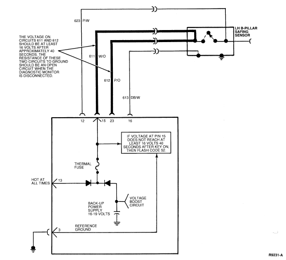
A back-up power supply is contained within the diagnostic monitor that
consists of 4 capacitors and a voltage boost circuit. The voltage boost circuit
charges the capacitors to 16-19 volts when the ignition switch is turned to ON.
The back-up power supply is connected through a diode to diagnostic monitor Pin
15 (Circuit 611, W/O). The resistance of Circuit 611 to ground is infinite
since it is an open circuit. This open circuit allows the capacitor to maintain
its higher voltage because there is no discharge path for the capacitor. The
diagnostic monitor measures the voltage on the back-up power supply capacitors.
If the voltage on the capacitors does not reach and maintain a minimum of 16
volts after approximately 45 seconds, the diagnostic monitor will flash
Diagnostic Trouble Code 52 to indicate low voltage in the back-up power supply
voltage boost circuit.
Possible Causes
Low back-up power supply voltage can be caused by:
- Resistance on Circuit 611 (W/O) to ground. Resistance to
ground on Circuit 611 or Circuit 612 (P/O) will cause the back-up power supply
capacitors to discharge and the boost circuit will not be able to boost the
voltage.
- Boost circuit failure within the diagnostic monitor. If the
voltage boost circuit in the diagnostic monitor is damaged it will not be able
to raise the back-up power supply voltage on the capacitor.
Electrical Schematic—Diagnostic Trouble Code 52

DIAGNOSTIC TROUBLE CODE 52
52-1 VERIFY CONDITION
- Count diagnostic trouble code.
 Yes
Yes
GO to 52-2.
 No
No
Read the normal operation description for this diagnostic
trouble code. EXAMINE the diagnostic trouble code schematic and look for areas
where intermittent conditions would occur (connectors, splices, crimps,
etc.).
DO NOT proceed with Pinpoint Test until the code is flashing! Failure to do so will result in needless replacement of the air bag system
components and repeat service.
52-2 CHECK DIAGNOSTIC MONITOR
- Turn ignition switch from OFF to RUN.
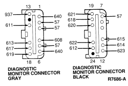
- Measure voltage between Pin 15 (Circuit 611, W/O) and Pin 3 (Ground).
Is voltage measured within 16-19 volts?
 Yes
Yes
REPLACE diagnostic monitor. RECONNECT system. VERIFY system.
REACTIVATE system.  No
No
GO to 52-3.
52-3 CHECK FOR OPEN IN CIRCUIT 611
- Turn ignition switch OFF.
- Disconnect diagnostic monitor.
- Set ohmmeter to 200 K scale or AUTO.
- Measure resistance of Pin 15 (Circuit 611, W/O) to Pin 3 (Ground).
Is reading infinite (open)?

 Yes
Yes
REPLACE diagnostic monitor. RECONNECT system. VERIFY system.
REACTIVATE system.  No
No
GO to 52-4.
52-4 MEASURE RESISTANCE OF CIRCUIT 611
- Disconnect LH B-pillar safing sensor.
- Measure resistance between Pin 15 (Circuit 611, W/O) and Pin 3 (Ground).
Is reading infinite (open)?
 Yes
Yes
GO to 52-5.
 No
No
LOCATE and SERVICE short to ground in Circuit 611, W/O.
RECONNECT system. VERIFY system. REACTIVATE system.
52-5 CHECK FOR SHORT IN SENSOR
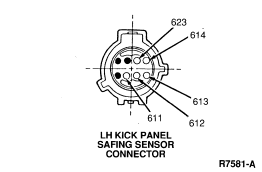
- Measure resistance of W/O wire in safing sensor connector to sheet metal
ground.
Is reading infinite (open)?

 Yes
Yes
LOCATE and SERVICE short to ground in Circuit 612 (P/O).
RECONNECT system. VERIFY system. REACTIVATE system.  No
No
REPLACE safing sensor. RECONNECT system. VERIFY system.
REACTIVATE system.
 No
No Yes
Yes No
No
 Yes
Yes No
No Yes
Yes No
No
 Yes
Yes No
No