Section 01-20B: Restraints, Passive—Supplemental Air Bag System | 1993 Mustang Workshop Manual |
DIAGNOSIS AND TESTING
Diagnostic Trouble Code 46
LH Primary Crash Sensor Not Mounted To Vehicle Properly
Normal Operation
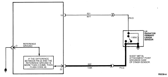
The diagnostic monitor measures the resistance between Pin 22 (Circuit
622, T/BK) and Pin 3 (diagnostic monitor reference ground). If the diagnostic
monitor measures a difference of more than 2.0 ohms between Pin 22 and Pin 3,
it will flash out Diagnostic Trouble Code 46.
Note that Circuit 622 (T/BK) is attached to the side of the LH primary
crash sensor case. In addition, the case is grounded to the vehicle.
Possible Causes
High resistance on Pin 22 (Circuit 622, T/BK) to ground can be caused by:
- A poor connection due to loose mounting, dirt, or corrosion at the LH
primary crash sensor mounting location.
- An open or damaged wire in Circuit 622 (T/BK) from Pin 22 of
the diagnostic monitor harness connector to LH primary crash sensor.
- An open circuit inside LH radiator primary crash sensor.
Electrical Schematic—Diagnostic Trouble Code 46

DIAGNOSTIC TROUBLE CODE 46
46-1 VERIFY CONDITION
- Count diagnostic trouble code.
 Yes
Yes
GO to 46-2.
 No
No
Read the normal operation description for this diagnostic
trouble code. EXAMINE the diagnostic trouble code schematic and look for areas
where intermittent conditions would occur (connectors, splices, crimps,
etc.).
DO NOT proceed with Pinpoint Test until the code is flashing!
Failure to do so will result in needless replacement of the air bag system
components and repeat service.
46-2 CHECK RESISTANCE
- Deactivate system. Leave positive battery cable disconnected.
- Disconnect diagnostic monitor.
- Set ohmmeter on lowest ohm scale possible (200 ohms or AUTO).
- Zero ohmmeter. Record resistance reading with two leads together.
- Measure resistance between Pin 22 and Pin 3 (ground).
- Subtract reading recorded above.
Is result greater than 2 ohms?

 Yes
Yes
GO to 46-3.
 No
No
REPLACE diagnostic monitor. RECONNECT system. VERIFY system.
REACTIVATE system.
46-3 ISOLATE CONCERN
- Disconnect LH primary crash sensor from harness.
- Measure resistance between Circuit 622 (T/BK) in sensor connector and a
nearby, good chassis ground. Make sure that this ground is clean and bare.
Is the resistance less than 2 ohms?
 Yes
Yes
INSPECT Circuit 622 (T/BK) (between Pin 22 and sensor for open
circuit. CHECK all interconnects and splices for poor connections. SERVICE any
poor connections. RECONNECT system. VERIFY system. REACTIVATE system.  No
No
REMOVE screws retaining sensor. CLEAN mounting surface of
sensor and chassis. INSTALL sensor. TIGHTEN screws to proper specification. GO
to 46-4.
46-4 CLEAN AND MEASURE RESISTANCE OF SENSOR TO GROUND
- Measure resistance between Circuit 622 (T/BK) in sensor connector and a
good chassis ground.
Is resistance less than 2 ohms?
 Yes
Yes
RECONNECT system. VERIFY system. REACTIVATE system.  No
No
REPLACE primary crash sensor. RECONNECT system. VERIFY system.
REACTIVATE system.
 No
No
 Yes
Yes No
No Yes
Yes No
No Yes
Yes No
No