Section 01-20B: Restraints, PassiveŚSupplemental Air Bag System | 1993 Mustang Workshop Manual |
DIAGNOSIS AND TESTING
Diagnostic Trouble Code 32
Driver Side Air Bag Circuit High Resistance Or Open
Normal Operation
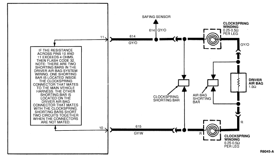
The diagnostic monitor measures the resistance across Pin 10 (Circuit
615, GY/W) and Pin 11 (Circuit 614, GY/O) every time the ignition switch is
turned to the ON position. Normal resistance across these circuits is between
1.5 ohms and 2.0 ohms. This resistance comes from the air bag itself
(approximately 1.0 ohm) and the clockspring windings (approximately 0.25 to 0.5
ohm per winding, two windings in all). If the resistance across these two
circuits exceeds 4.0 ohms, the diagnostic monitor will flash Diagnostic Trouble
Code 32.
NOTE: The connectors for the air bag and the clockspring have metal spring
clips that act as shorting bars. These shorting bars are built into the plastic
hardshell connectors. The shorting bars are designed to short Circuit 614 and
615 together when the connectors are not mated. Do not attempt to remove
the air bag shorting bar and measure the resistance of the air bag.
The clockspring shorting bar may be removed to measure the
clockspring resistance. Use extreme care when reinstalling the shorting bar to
ensure it is installed correctly.
Possible Causes
Excessive resistance across Pins 10 and 11 can be caused by:
- A poor connection where the clockspring connects into the main wiring
harness. The clockspring connector at the base of the steering column
may have excessive resistance between the male and female terminals in the
connector, or across the terminal crimps.
- An open circuit or high resistance in the clockspring windings
inside the clockspring assembly.
- An open circuit or high resistance in the wiring harness in either
Circuit 614 (GY/O) or Circuit 615 (GY/W).
- An open circuit or high resistance in the driver side air bag.
DO NOT attempt a direct resistance measurement of the air bag. Follow the
diagnostic procedures to determine if the air bag resistance is higher than
normal.
Electrical SchematicŚDiagnostic Trouble Code 32
DIAGNOSTIC TROUBLE CODE 32
32-1 VERIFY CONDITION
- Count diagnostic trouble code.
 Yes
Yes
GO to 32-2.
No
Read the normal operation description for this diagnostic
trouble code. EXAMINE the diagnostic trouble code schematic and look for areas
where intermittent conditions would occur (connectors, splices, crimps,
etc.).
DO NOT proceed with Pinpoint Test until the code is flashing!
Failure to do so will result in needless replacement of the air bag system
components and repeat service.
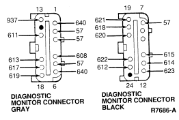
32-2 MEASURE RESISTANCE
- Disconnect diagnostic monitor.
- Set ohmmeter on lowest scale possible (200 ohms or AUTO).
- "Zero" ohmmeter by touching leads together and record resistance reading.
- Remove plastic locking wedge from Black harness connector.
- Measure resistance across Pin 11 Circuit 614 (GY/O) and Pin 10 Circuit
615 (GY/W). Record measurement. Subtract this reading from reading made when
zeroing ohmmeter.
Is result less than 2.3 ohms?
Yes
MAKE SURE that locking wedge has been removed from Black
harness connector. MAKE SURE to use 2 ohm air bag simulator and not a jumper
wire. REPEAT the measurement. No
GO to 32-3.
32-3 VERIFY RESISTANCE READING
Is result greater than 3.0 ohms?
Yes
GO to 32-5.
No
GO to 32-4.
32-4 VERIFY CONDITION
- Reconnect diagnostic monitor.
- Turn ignition switch from OFF to RUN.
Is code 32 still flashing?
Yes
REPLACE diagnostic monitor. RECONNECT system. VERIFY system.
REACTIVATE system. No
INSPECT diagnostic monitor harness connector for improperly
retained Pins 10 and 11. If OK, INSPECT clockspring wiring in steering wheel
for damaged wiring. If OK, RECONNECT driver air bag and VERIFY system. If Code
32 is now flashing, REPLACE driver air bag. RECONNECT system. VERIFY system.
REACTIVATE system.
32-5 ISOLATE CONCERN
- Disconnect clockspring at base of the steering column.
- Install air bag simulator on main wiring harness at base of steering
column.
- Measure resistance across Pin 10 (Circuit 615 (GY/W)) and Pin 11
(Circuit 614 (GY/O)) on diagnostic monitor harness connector.
- Subtract this reading from reading made when zeroing ohmmeter.
Is result equal to 2 ohms ± 0.2 ohm?
Yes
REPLACE contact assembly (clockspring). REFER to 11-04 for
Removal and Installation procedures. RECONNECT system. VERIFY system.
REACTIVATE system. No
VERIFY that air bag simulator resistance measures 2 ohms ±
0.2 ohm. If OK, LOCATE and SERVICE open in Circuit 614 or
615. RECONNECT system. VERIFY system. REACTIVATE system.