Section 01-20B: Restraints, Passive—Supplemental Air Bag System | 1993 Mustang Workshop Manual |
DIAGNOSIS AND TESTING
Diagnostic Trouble Code 24
Safing Sensor Diagnostic Circuit Open Or Low Resistance In A Primary
Crash Sensor
Normal Operation
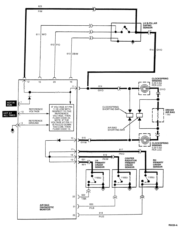
Each primary crash sensor has an internal resistor. The diagnostic
monitor uses the resistor in the primary crash sensors in combination with the
two resistors inside the diagnostic monitor to create a tightly controlled
diagnostic voltage at Pin 11 (Circuit 614, GY/O). The primary crash sensors are
tied together inside the diagnostic monitor at Pins 17 (Circuit 617, PK/O), 18
(Circuit 619, PK/W) and 19 (Circuit 621, W/Y). Therefore, the resistors in the
sensors are connected in parallel. The parallel combination of all three sensor
resistors should be equal to 393 ohms. The resistance of each sensor should be
1180 (± 20 ohms) ohms.
The resistors inside the diagnostic monitor are connected to Pins 11
(Circuit 614, GY/O) and 12 (Circuit 623, P/W) and are equal in value. Note that
Circuits 614 and 623 are tied together inside the safing sensor. Therefore, the
two resistors inside the diagnostic monitor are connected in parallel and will
function the same as one resistor of half the original value. Current flows
from Pins 1 and 6 through the resistors, out to Circuits 614 (GY/O) and 623
(P/W) on Pins 11 and 12, through the LH B-pillar safing sensor and out to the
driver side air bag. Current flows through the driver side air bag and into Pin
10 (Circuit 615, GY/W). Current then flows from Pin 10 through the diode inside
the diagnostic monitor and out to the primary crash sensors through Pins 17, 18
and 19. The current flows through each primary crash sensor resistor and ends
at the case ground of each sensor. Pin 11 is the midpoint of the resistor
network and voltage at Pin 11 will change with vehicle charging system voltage.
The expected voltage at Pin 11 is shown in the table below. The diagnostic
monitor measures the vehicle charging system voltage at Pin 13 (battery input).
By measuring the voltage at Pin 13, the diagnostic monitor can accurately
predict what the voltage at Pin 11 should be in a normal functioning system.
If the connection between Circuits 614 (GY/O) and 623 (P/W) inside the
safing sensor is broken, then the resistor on Pin 12 is no longer in the
diagnostic circuit. Both resistors are needed to pull up the diagnostic voltage
to the correct value. In this situation, the resistor on Pin 11 is the only
resistor inside the diagnostic monitor pulling up the voltage. Therefore, the
voltage on Pin 11 will be half of the normal expected voltage and the voltage
on Pin 12 will be about equal to the vehicle charging system voltage. The
diagnostic monitor does not measure the voltage on Pin 12, so the monitor bases
its decision strictly on the voltage at Pin 11. If the voltage at Pin 11 is
lower than it should be, the monitor will flash Diagnostic Trouble Code 24.
Another situation that can cause low voltage at Pin 11 is a drop in primary
crash sensor resistance (resistance is too low). If this occurs, the voltage at
Pin 11 will be pulled down to a lower than normal value because the parallel
combination resistance of the primary crash sensors will be less than 393 ohms.
In this situation, the voltage at Pins 11 and 12 will be identical, but the
monitor does not measure the voltage at Pin 12. Therefore, a primary crash
sensor with low resistance may cause low voltage at Pin 11 and the monitor will
flash Diagnostic Trouble Code 24 on the air bag indicator.
Possible Causes
Low voltage at Pin 11 and high voltage at Pin 12 can be caused by:
- An open circuit or high resistance in the wiring harness in Circuit
614 (GY/O) or 623 (P/W).
- An open circuit or high resistance inside the safing sensor across
Circuit 614 (GY/O) and Circuit 623 (P/W) wires.
Low voltage on both Pins 11 and 12 can be caused by:
- Resistance to ground on Circuit 614 or 623. Circuits 614 and
623 should be open circuits to ground when the diagnostic monitor is
disconnected from the harness. Resistance to ground on these circuits can cause
a drop in the diagnostic voltage on both circuits.
- Low resistance in one or more of the primary crash sensors. If
the resistance of one or more of the primary crash sensors is lower than
normal, the voltage on Pin 11 will be pulled down too low.
- A poor ground on Pin 3 of the diagnostic monitor may cause
voltage to appear on the diagnostic monitor ground reference. Any voltage on
the ground reference will cause the diagnostic monitor to measure the voltage
at Pin 11 as low, even though the voltage on Pin 11 with respect to sheet metal
is normal.
- Intermittent battery voltage at Pin 13 can cause the reference
voltage inside the diagnostic monitor to fluctuate and can cause Diagnostic
Trouble Code 24 in some circumstances.
CHARGING SYSTEM VOLTAGE
| Charging System Voltage |
Voltage at PIN NO. 11 |
Voltage at PIN NO. 12 |
| 9.0 |
1.9 |
1.9 |
| 9.5 |
2.0 |
2.0 |
| 10.0 |
2.1 |
2.1 |
| 10.5 |
2.2 |
2.2 |
| 11.0 |
2.3 |
2.3 |
| 11.5 |
2.4 |
2.4 |
| 12.0 |
2.5 |
2.5 |
| 12.5 |
2.6 |
2.6 |
| 13.0 |
2.7 |
2.7 |
| 13.5 |
2.7 |
2.7 |
| 14.0 |
2.9 |
2.9 |
| 14.5 |
3.0 |
3.0 |
| 15.0 |
3.1 |
3.1 |
| 15.5 |
3.2 |
3.2 |
| 16.0 |
3.3 |
3.3 |
Electrical Schematic—Diagnostic Trouble Code 24

DIAGNOSTIC TROUBLE CODE 24
24-1 VERIFY CONDITION
- Count diagnostic trouble code.
 Yes
Yes
GO to 24-2.
 No
No
Read the normal operation description for this diagnostic
trouble code. EXAMINE the diagnostic trouble code schematic and look for areas
where intermittent conditions would occur (connectors, splices, crimps,
etc.).
DO NOT proceed with Pinpoint Test until the code is flashing!
Failure to do so will result in needless replacement of the air bag system
components and repeat service.
24-2 CHECK SAFING SENSOR FEED/RETURN
- Turn key ignition switch from OFF to RUN.
Are voltages at these terminals within specification
(± 1 volt)?
 Yes
Yes
CHECK "HOT AT ALL TIMES" voltage feed circuit, from fuse panel
to Pin 13 (Circuit 937) of diagnostic monitor harness connector for
intermittent open circuits. If none are found, REPLACE diagnostic monitor.
RECONNECT system. VERIFY system. REACTIVATE system.  No
No
Both terminals measure low voltage, GO to 24-3.
| |
|
Pin 12 measures high and Pin 11 measures low, GO to 24-4.
|
24-3 CHECK PRIMARY SENSOR RESISTANCE
- Turn ignition switch OFF.
- Disconnect diagnostic monitor.
- Disconnect battery ground cable.
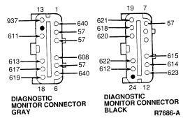
- Using Pin 3 as a ground, measure resistance of following Pins in
diagnostic monitor harness connector:
|
Specification |
| Pin 17 (Circuit 617 - PK/O) |
1180 ± 20 ohms |
| Pin 18 (Circuit 619 - (PK/W) |
1180 ± 20 ohms |
| Pin 19 (Circuit 621 - W/Y) |
1180 ± 20 ohms |
Are all measurements within specification?

 Yes
Yes
GO to 24-6.
 NO
NO
GO to 24-5.
24-4 CHECK SAFING SENSOR
- Turn key ignition switch from OFF to RUN.
- Disconnect LH B-pillar safing sensor.
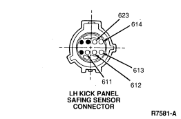
- Measure resistance across Circuits 614 (GY/O) and 623 P/W in sensor
connector.
Is there an open circuit across Circuit 614 (GY/O) and Circuit 623
(P/W)?

 Yes
Yes
LOCATE and SERVICE open in Circuit 614 (GY/O) or Circuit 623
(P/W). RECONNECT system. VERIFY system. REACTIVATE system.  No
No
REPLACE LH B-pillar safing sensor. RECONNECT system. VERIFY
system. REACTIVATE system.
24-5 ISOLATE CONCERN
- Disconnect the abnormal primary crash sensor from harness.
- Measure resistance directly across the two circuits in the primary
sensor connectors.
Is resistance within 1180 ± 20 ohms?
 Yes
Yes
LOCATE and SERVICE short to ground in wiring harness on the
abnormal circuit. RECONNECT system. VERIFY system. REACTIVATE system.  No
No
REPLACE primary crash sensor. RECONNECT system. VERIFY system.
REACTIVATE system.
24-6 CHECK FOR SHORT TO GROUND
- Using Pin 3 as a ground, measure resistance of Pin 11 Circuit 614 (GY/O)
to ground (ohmmeter must be on 200K ohm scale or AUTO).
Is resistance infinite (open)?
 Yes
Yes
REPLACE diagnostic monitor. RECONNECT system. VERIFY system.
REACTIVATE system.  No
No
LOCATE and SERVICE short to ground in either Circuit 614
(GY/O), 615 (GY/W), 623 (P/W). CHECK air bag(s), clockspring, safing sensor for
internal shorts to ground. RECONNECT system. VERIFY system. REACTIVATE system.
 No
No Yes
Yes No
No
 Yes
Yes NO
NO
 Yes
Yes No
No Yes
Yes No
No Yes
Yes No
No