Section 01-20B: Restraints, Passive—Supplemental Air Bag System | 1993 Mustang Workshop Manual |
DIAGNOSIS AND TESTING
Diagnostic Trouble Code 13
Air Bag Or Crash Sensor Circuit Shorted To Ground
Normal Operation
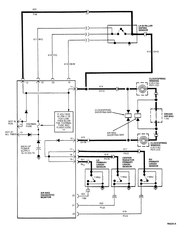
The diagnostic monitor measures the voltage at Pin 11 (Circuit 614, GY/O)
of the diagnostic monitor connector. The voltage at Pin 11 varies with charging
system voltage (the expected voltage at Pin 11 is shown in the chart below).
Note that Circuit 614 is connected to Circuit 615 (GY/W) through the driver
side air bag. Also, note that Circuit 615 is connected to the primary crash
sensor feed circuits (617 (PK/O), 619 (PK/W) and 621, W/Y) through a diode
inside the diagnostic monitor. If the diagnostic monitor measures a voltage of
2.0 volts or less at Pin 11, the monitor will flash out Diagnostic Trouble Code
13 to indicate a possible short to ground on this circuit ( refer to Possible
Causes for additional circuits that may be shorted to ground). When flashing
Diagnostic Trouble Code 13, the diagnostic monitor blows its internal thermal
fuse. This disables the air bag deployment circuit. If the voltage at Pin 11
returns to normal, a Diagnostic Trouble Code 51 will be present due to the open
thermal fuse (refer to Diagnostic Trouble Code 51 as outlined).
NOTE: Diagnostic Trouble Code 13 will flash only while the short to ground is
present.
Possible Causes
Low voltage at diagnostic monitor Pin 11 can be caused by:
- A short to ground within the wiring harness on Circuits 614 (GY/O),
615 (GY/W), 623 (P/W), 617 (PK/O), 619 (PK/W), or 621 (W/Y) causing the
diagnostic voltage to drop.
- An internal short to ground within the clockspring assembly
causing the driver side air bag circuit(s) to be shorted to ground.
- An internal short to ground within the safing sensor causing
Circuit 614 (GY/O) or 623 (P/W) to be shorted to ground.
- An internal short to ground within one or more of the crash
sensors causing Circuits 617 (PK/O), 619 (PK/W) and 621 (W/Y) to be
shorted to ground.
- An internal short to case ground within the driver side air bag.
NOTE: Circuits 617 (PK/O), 619 (PK/W) and 621 (W/Y) are all connected together
inside the diagnostic monitor. Therefore, a short to ground on any of these
circuits will short all of the circuits to ground.
CHARGING SYSTEM VOLTAGE
| Charging System Voltage |
Voltage at PIN NO. 11 |
| 9.0 |
1.9 |
| 9.5 |
2.0 |
| 10.0 |
2.1 |
| 10.5 |
2.2 |
| 11.0 |
2.3 |
| 11.5 |
2.4 |
| 12.0 |
2.5 |
| 12.5 |
2.6 |
| 13.0 |
2.7 |
| 13.5 |
2.7 |
| 14.0 |
2.9 |
| 14.5 |
3.0 |
| 15.0 |
3.1 |
| 15.5 |
3.2 |
| 16.0 |
3.3 |
Electrical Schematic—Diagnostic Trouble Code 13

DIAGNOSTIC TROUBLE CODE 13
13-1 VERIFY CONDITION
- Count diagnostic trouble code.
 Yes
Yes
GO to 13-2.
 No
No
Read the normal operation description for this diagnostic
trouble code. EXAMINE the diagnostic trouble code schematic and look for areas
where intermittent conditions would occur (connectors, splices, crimps,
etc.)
DO NOT proceed with pinpoint test until the code is flashing!
Failure to do so will result in needless replacement of the air bag system
components and repeat service.
13-2 DEACTIVATE SYSTEM
NOTE: Never attempt to replace diagnostic monitor with a diagnostic trouble
code 13 present, unless instructed to do so.
Does air bag indicator flash a diagnostic trouble code 13?
 Yes
Yes
GO to 13-5.
 No
No
GO to 13-3.
13-3 CHECK AIR BAG(S) AND CLOCKSPRING
- Inspect clockspring wiring in steering wheel and driver air bag for
damaged, chafed, or pinched wires.
Are any component wires damaged?
 Yes
Yes
REPLACE component(s) which have damaged wires. GO to Diagnostic Trouble Code 51
. No
No
GO to 13-4.
13-4 VERIFY SHORT IN AIR BAG(S)
- Measure the resistance between either of the terminals in the air bag
connector and the metal case of the driver air bag assembly.
Is the resistance reading infinite (open)?
 Yes
Yes
REPLACE clockspring. GO to Diagnostic Trouble Code 51. No
No
REPLACE the driver air bag assembly. GO to Diagnostic Trouble Code 51.
13-5 INSTALL AIR BAG SIMULATOR AT BASE OF STEERING COLUMN
- Remove driver air bag simulator.
- Disconnect black 3-way connector containing Circuits 614 (GY/O) and 615
(GY/W) at base of steering column.
- Install air bag simulator on vehicle harness side at base of steering
column.
Does air bag indicator flash a diagnostic trouble code 13?
 Yes
Yes
GO to 13-6.
 No
No
REPLACE clockspring. GO to Diagnostic Trouble Code 51.
13-6 REMOVE AIR BAG SIMULATOR FROM BASE OF STEERING COLUMN
- Remove air bag simulator from vehicle harness connector at base of
steering column.
Does air bag indicator flash a diagnostic trouble code 13?
 Yes
Yes
GO to 13-7.
 No
No
LOCATE and SERVICE short to ground in wiring harness Circuit
615 (GY/W). GO to Diagnostic Trouble Code 51.
13-7 CHECK FOR SHORTED WIRING
- Disconnect diagnostic monitor.
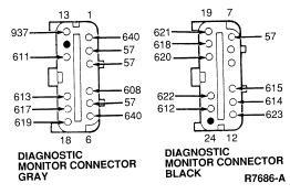
- Measure resistance from diagnostic monitor connector Pin 17 (Circuit
617, PK/O), Pin 18 (Circuit 618, PK/W), Pin 19 (Circuit 621, W/Y) and Pin 11
(Circuit 614, GY/O) to ground. Normal resistance to ground on these pins are as
follows:
- Pin 11 - Open (infinite)
- Pin 17 - 1180 ohms ± 20 ohms
- Pin 18 - 1180 ohms ± 20 ohms
- Pin 19 - 1180 ohms ± 20 ohms
Are any of these circuits shorted to ground?

 Yes
Yes
If Pin 11 is shorted to ground, GO to 13-8.
| |
|
If Pin 17, 18 or 19 is shorted to ground, GO to 13-10.
|
 No
No
REPLACE diagnostic monitor. RECONNECT system. VERIFY system.
REACTUATE system.
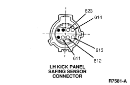
13-8 CHECK LH B-PILLAR SAFING SENSOR CIRCUIT
- Disconnect LH B-pillar safing sensor connector.
Does air bag indicator flash a diagnostic trouble code 13?
 Yes
Yes
LOCATE and SERVICE short to ground in wiring harness Circuit
614 (GY/O). GO to Diagnostic Trouble Code 51. No
No
GO to 13-9.
13-9 VERIFY SHORT TO GROUND IN LH B-PILLAR SAFING SENSOR
- Measure resistance from safing sensor connector Circuit 614 (GY/O) to
ground.
Is resistance less than 10 ohms?

 Yes
Yes
REPLACE LH B-pillar safing sensor. GO to Diagnostic Trouble Code 51. No
No
LOCATE and SERVICE short to ground in wiring harness Circuit
623 (P/W). GO to Diagnostic Trouble Code 51.
13-10 CHECK SHORT TO GROUND IN CRASH SENSORS
- If Pin 17 was shorted to ground, disconnect RH headlamp primary crash
sensor. If Pin 18 was shorted to ground, disconnect center radiator primary
crash sensor. If Pin 19 was shorted to ground, disconnect LH headlamp primary
crash sensor.
- Measure the resistance across the two circuits in the disconnected
sensor connector.
Is the resistance less than 750 ohms?
 Yes
Yes
REPLACE sensor. GO to Diagnostic Trouble Code 51. No
No
LOCATE and SERVICE short to ground in wiring harness Circuits
617 (PK/O), 619 (PK/W) or 621 (W/Y). GO to Diagnostic Trouble Code 51.
 No
No Yes
Yes No
No Yes
Yes No
No WARNING: USE A HANDHELD DIGITAL OHMMETER WITH LESS THAN 10 MA SHORT-CIRCUIT
CURRENT ON THE LOWEST RESISTANCE SCALE POSSIBLE (TYPICALLY 2000 OHM SETTING).
FAILURE TO USE A METER OF THIS TYPE MAY CAUSE PERSONAL INJURY DUE TO AIR BAG
DEPLOYMENT.
 Yes
Yes No
No Yes
Yes No
No Yes
Yes No
No
 Yes
Yes No
No Yes
Yes No
No
 Yes
Yes No
No Yes
Yes No
No