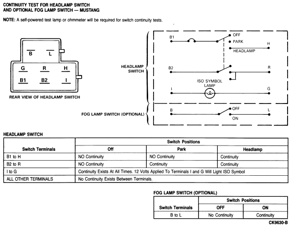
Section 17-01: Lighting, Exterior
1993 Mustang Workshop Manual
DIAGNOSIS AND TESTING

Electrical Lamps

HEADLAMPS
ConditionPossible SourceAction
  • All Exterior Lamps Do Not Light
  • Loose wiring connections.
  • Check and secure connection at headlamp switch and dash panel connector.
 
  • Open wiring.
  • Check power to and from headlamp switch. Service as necessary.
 
  • Damaged headlamp switch.
  • Replace headlamp switch.
  • One Headlamp Does Not Work
  • Loose connection
  • Secure connection at headlamp.
 
  • Bad ground.
  • Check ground at headlamp.
 
  • Bulb burned out.
  • Replace bulb.
 
  • Corroded or damaged connector.
  • Replace as required.
  • All Headlamps Out. Park and Tail Lamps OK
  • Loose connections.
  • Check and secure connections at dimmer switch and headlamp switch.
 
  • Damaged dimmer switch.
  • Check dimmer switch operation. Inspect for corroded connector. Replace if necessary.
 
  • Damaged headlamp switch.
  • Replace if necessary.
 
  • Open wiring or poor ground.
  • Service as necessary.
TAIL LAMPS
ConditionPossible SourceAction
  • One Tail Lamp Out
  • Bulb burned out.
  • Replace bulb.
 
  • Open wiring or poor ground.
  • Service as necessary.
 
  • Corroded bulb socket.
  • Service or replace socket.
  • All tail lamps, park lamps, and instrument panel lamps out—headlamps OK
  • Blown fuse in fuse panel.
  • Service as necessary.
 
  • Loose connections.
  • Secure wiring connections where accessible.
 
  • Open wiring.
  • Service as necessary.
 
  • Damaged headlamp switch.
  • Service headlamp switch.
BACKUP LAMPS
ConditionPossible SourceAction
  • Backup Lamps — One Does Not Function
  • Blown fuse in fuse panel.
  • Replace fuse.
 
  • Bulb burned out.
  • Replace bulb.
 
  • Loose connections.
  • Tighten connectors.
 
  • Open wiring.
  • Service as necessary.
  • Both Lamps Do Not Function
  • Fuse burned out.
  • Check a circuit that shares the same fuse. Replace fuse.
 
  • Backup lamp switch out of adjustment.
  • Adjust switch.
 
  • Damaged backup lamp switch.
  • Replace switch.
 
  • Loose connections.
  • Tighten connectors.
 
  • Open wiring.
  • Service as required.
PARKING LAMPS
ConditionPossible SourceAction
  • One Parking Lamp Does Not Light
  • Loose connections.
  • Tighten connections.
 
  • Bulb burned out.
  • Replace bulb.
 
  • Open wiring or poor ground.
  • Check for corroded socket. Service as required
  • Both Parking Lamps Do Not Light
  • Loose connections.
  • Tighten connections.
 
  • Open wiring.
  • Check for corroded socket. Service as required.
 
  • Bulbs burned out.
  • Replace bulbs.
FRONT SIDE MARKER LAMPS
ConditionPossible SourceAction
  • Front Side Marker Lamp Does Not Light—Tail Lamps OK
  • Loose connections.
  • Tighten connections.
 
  • Bulb burned out.
  • Replace bulb.
 
  • Open wiring.
  • Check socket for corrosion and good ground. Service as required.
STOPLAMPS
ConditionPossible SourceAction
  • Stoplamps Do Not Light
  • Fuse burned out.
  • Replace fuse or CB. If device blows again, check for short circuit.
 
  • Problem in turn signal circuit or switch.
  • Service turn signal circuit or replace turn signal.
 
  • Loose connections.
  • Secure connections at stoplamp switch.
 
  • Stoplamp switch inoperative.
  • Replace stoplamp switch.
 
  • Open wiring.
  • Service as required.
  • Hi-Mount Stoplamp Out
  • Bulb burned out.
  • Replace bulb.
 
  • Open wiring or poor ground.
  • Service as necessary.
 
  • Corroded bulb socket.
  • Service or replace socket.
TURN SIGNAL LAMPS
ConditionPossible SourceAction
  • One or More Lamps Inoperative
  • Bulb burned out.
  • Replace bulb.
 
  • Loose connections.
  • Secure connections.
 
  • Open wiring.
  • Service as required.
 
  • Turn signal switch inoperative.
  • Replace turn signal switch.
  • All Lamps Inoperative
  • Fuse burned out.
  • Replace fuse or CB. If device blows again, check for short circuit.
 
  • Turn signal flasher inoperative
  • Replace flasher.
 
  • Loose connections.
  • Tighten connections.
 
  • Open wiring.
  • Service as required.
 
  • Turn signal switch inoperative.
  • Replace turn signal switch.
HAZARD FLASHER LAMPS
ConditionPossible SourceAction
  • Lamps Do Not Flash
  • Turn signal operation improper.
  • Service turn signal system.
 
  • Fuse burned out.
  • Replace fuse. If fuse blows again, check for a short circuit.
 
  • Hazard flasher inoperative.
  • Replace flasher.
 
  • Open wiring.
  • Service as required.
 
  • Hazard flasher switch inoperative.
  • Service or replace the turn signal switch assembly, which includes the hazard flasher switch.


FOG LAMP SWITCH TEST


A0 CHECK CONNECTOR

Yes
Power available at connector. GO to A1.

No
No power at connector. TRACE circuit and SERVICE as necessary. RETEST.


A1 CHECK SWITCH

Yes
Switch OK.

No
REPLACE switch and RETEST.


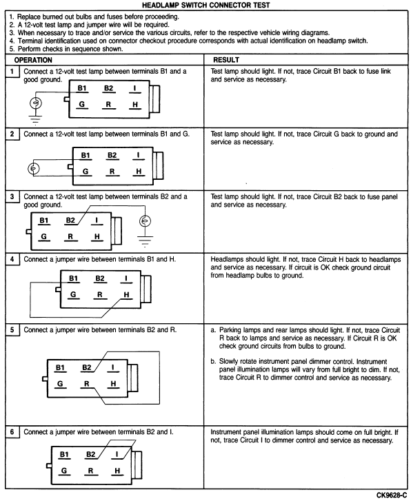
Headlamp Switch Diagnosis 
NOTE: Replace burned out bulbs or fuses before proceeding.
ConditionPossible SourceAction
  • Headlamps Do Not Work Park and Tail Lamps OK
  • Open or shorted wiring.
  • Check wiring and connections between power source and headlamp switch and between headlamp switch and lamps. Service as necessary.
 
  • Poor ground connections.
  • Check and service as necessary.
 
  • Damaged dimmer switch.
  • Check dimmer switch, replace if necessary.
 
  • Damaged DRL relay.
 
  • Damaged headlamp switch.
  • Check headlamp switch, replace if necessary.
  • All Exterior Lamps Do Not Work
  • Open or shorted wiring.
  • Check wiring and connections between power source and headlamp switch and between headlamp switch and dash panel connector.
 
  • Damaged headlamp switch.
  • Check headlamp switch, replace if necessary.
  • Headlamps Flash On and Off
  • Shorted circuit.
  • Check wiring and connections between headlamp switch and headlamps.
 
  • Overloaded headlamp switch.
  • Check headlamp load.
 
  • Damaged headlamp switch.
  • Replace headlamp switch.
 
  • Damaged terminals.
  • Service/replace damaged terminals.
  • All Exterior Lamps Do Not Work Headlamps OK
  • Blown Fuse.
  • Replace fuse.
 
  • Open wiring or poor ground.
  • Check wiring and connections between power source and headlamp switch and between headlamp switch and lamps. Service as necessary.
 
  • Damaged headlamp switch.
  • Check headlamp switch, replace as necessary.
  • Instrument Panel Lamps Do Not Work or Will Not Dim
  • Blown fuse.
  • Replace fuse.
 
  • Open or shorted wiring.
  • Check wiring between headlamp switch and lamps.
 
  • Damaged headlamp switch.
  • Check headlamp switch, replace if necessary.
  • Dome Lamps Will Not Work
  • Blown fuse.
  • Replace fuse.
 
  • Open or shorted wiring.
  • Check wiring and connections between headlamp switch and dome lamp and between headlamp switch and fuse panel.
 
  • Damaged headlamp switch.
  • Check headlamp switch, replace if necessary.


Daytime Running Lamp (DRL) Diagnosis 
ConditionPossible SourceAction
  • With ignition in Run, parking brake fully released, and the headlamp switch Off or in the parking lamp positon:
  • DRL module is not installed.
  • Install module.
  • High beams are not on at all
  • Poor connection at module.
  • Check and service as necessary.
  • High beam indicator ON
  • Open or shorted wiring.
  • Check wiring to low beams.
  • High beams are on at FULL intensity
  • Damaged DRL module.
  • Check for 12 volts to Pins 2 (Circuit 640, R/Y) and 4 (Circuit 296, W/P) of connector.
  • Cornering lamps are on at reduced intensity when using turn signal
  • Multi-function switch is in high beam position. This is expected for NON AutoLamp/AutoDim vehicles.
  • Check parking brake switch, the wire to the switch should not be grounded.
  • Replace module.
  • None required.
  • With ignition OFF, parking brake fully released, and the headlamp switch Off or in the parking lamp position:
  • Damaged ignition switch.
  • Check the ignition switch and replace as necessary.
 
  • Shorted wiring.
  • Check Pin 2 (Circuit 640, R/Y) on DRL connector. If 12 volts exists, service wiring.
  • High beams are on at reduced intensity
  • Damaged DRL module.
  • Check Pin 2 (Circuit 640 R/Y) on DRL connector. If 12 volts does not exist, replace DRL module.
  • With ignition in RUN, parking brake applied, and the headlamp switch Off or in the parking lamp position:
  • Open wiring or poor ground.
  • Check wiring and connections between DRL module and parking brake switch (Pin 6 Circuit 977, P/W).
  • High beams are on at reduced intensity
  • Damaged parking brake switch.
  • Check switch and replace as necessary.
 
  • Damaged DRL module.
  • Replace as necessary.
  • With headlamp switch On:
  • High beams are on at reduced intensity
  • Damaged headlamp switch.
 
  • Damaged DRL module.
  • Remove module. If headlamps are on, replace module.
  • With headlamps in the high beam position:
  • High beams on, but there is not an indicator in instrument panel
  • Burned out bulb.
  • Check and replace as necessary.
 
  • Open in wiring.
  • Check wiring and connections between DRL module and the indicator lamp.
 
  • Damaged DRL module.
  • Place a jumper wire between Pins 1 (Circuit 932, GY/W) and 8 (Circuit 12, LG/BK) in the DRL connector. If indicator turns On, replace the DRL module.


Daytime Running Lamp (DRL) Module Harness Connector


NOTE: Prior to beginning test, turn ignition off, apply parking brake and turn off all lamps (including autolamp and auto dim).


DAYTIME RUNNING LAMP (DRL) WIRING — DIAGNOSIS
Test Step Voltage by Pin Number
1. Disconnect module. Pin 4 should be 12 volts.
Pins 1, 2, 3, 6, 7 and 8 should be 0 volts.
2. Start vehicle. Pins 2, 3 and 4 should be 12 volts.
Pins 1, 6, 7 and 8 should be 0 volts.
3. Release parking brake. Pins 2, 3 and 4 should be 12 volts.
Pins 1, 6, 7 and 8 should be 0 volts.
4. Turn on headlamps (LO beams). Pins 2, 3, 4 and 7 should be 12 volts.
Pins 1, 6 and 8 should be 0 volts.
5. Turn on headlamps (HI beams). Pins 2, 3, 4 and 8 should be 12 volts.
Pins 1, 6, and 7 should be 0 volts.
6. Connect Pins 1 and 8. Pins 1, 2, 3, 4, and 8 should be 12 volts.
The HI beam indicator should be illuminated.
Pins 6 and 7 should be 0 volts.
7. Connect Pins 3 and 6. Pins 1, 2, 3, 4, 6 and 8 should be 12 volts.
The HI beam indicator should be illuminated.
Pin 7 should be 0 volts.
8. Apply parking brake. Pins 1, 2, 4 and 8 should be 12 volts.
The HI beam indicator should be illuminated.
Pins 3, 6 and 7 should be 0 volts.