Section 07-01A: Transmission, Automatic, A4LD | 1993 Mustang Workshop Manual |
DIAGNOSIS AND TESTING
Quick Tests
The Quick Tests are in the Powertrain Control/Emissions Diagnosis
Manual. These tests are
used to diagnose the PCM, sensors and actuators.
The following is a guide for using the Quick Tests, with some special
considerations to remember.
Quick Test 1.0 Visual Check
Perform the Visual Check as outlined in the Powertrain Control/Emissions
Diagnosis Manual.
Quick Test 2.0 Vehicle Preparation and Equipment Hookup
- Connect SUPER STAR II Tester 007-0041A or equivalent to Data Link
connector. The following are procedures to run the EEC-IV On-Board Diagnostics.
NOTE: The SUPER STAR II Tester 007-0041A or equivalent must be used on fast
mode to properly display the Diagnostic Trouble Codes.
NOTE: The On-Board Diagnostics can be entered only once each time the key is
turned on. To re-enter the On-Board Diagnostics, turn the key off and wait 10
seconds.
- Transmission in PARK
- Emergency brake set
- Electrical accessories OFF (lamps, A/C, defrost, etc.). If A/C is ON,
fault code 539 will be set
- Engine at operating temperature
Quick Test 3.0 Key On, Engine Off (KOEO)
Some special considerations for Key On, Engine Off On-Board Diagnostics
include the following:
- The KOEO test provides both "hard" diagnostic trouble codes (DTCs)
(present at the time of testing) and continuous memory codes.
- Always service the "hard" DTCs first. These are displayed first on
the tester.
KOEO On-Board Diagnostics
NOTE: If SUPER STAR II Tester is unavailable, refer to the Powertrain
Control/Emissions Diagnosis Manual for alternate methods to run the On-Board Diagnostics.
- Activate On-Board Diagnostics by pressing center button on SUPER STAR II
Tester.
- Turn ignition switch to ON position.
- PCM will run On-Board Diagnostics and then output "hard" DTCs (or Code 11
or 111-pass test). "Hard" DTCs are repeated to make it easier to verify
sequence. After "hard" DTCs have been repeated (or Code 11 or 111 repeated) a
single pulse occurs (10) to signal that next set of DTCs will be from
continuous test (or Code 11 or 111-pass).
- To display codes unlatch center button and use memory buttons to scroll
through codes.
Quick Test 4.0 Continuous Test Memory Codes
Continuous memory codes are from concerns which were detected during
normal vehicle operation. These codes are retained for 40 warm-up cycles.
After servicing any KOEO or KOER "hard" DTCs and a pass code 11 or 111 is
received on both, service the continuous memory codes. Some special
considerations for continuous testing include the following:
Special Test Modes
NOTE: The wiggle test may also be entered by "latching" STI; ON, OFF, ON.
- Wiggle test mode:
- After all DTCs have been received the wiggle test mode is entered —
by pressing center button on STAR Tester twice. This will
unlatch and relatch STI.
- The wiggle test allows the technician to attempt to re-create an
intermittent malfunction. Tap, move and wiggle the suspected sensor and/or wire
harness. When a malfunction is detected the Self Test Output (STO) will be
turned on as long as the fault is present. STO ON will cause the STAR Tester to
sound a continuous tone. The Malfunction Indicator Lamp will also illuminate.
- Output cycling test mode:
- After all KOEO DTCs have been received, the output test mode is entered.
Actuator outputs will turn ON and OFF each time the throttle is depressed to
WOT and then returned to closed position.
Quick Test 5.0 Key On, Engine Running (KOER)
The Engine Running On-Board Diagnostics provides "hard" DTCs only. Some
special considerations for Engine Running On-Board Diagnostics include the
following:
- After the engine ID code, (STO LO flashes) push and release the brake
pedal, turn steering wheel half turn and release.
- If a DTC appears after the KOER test, a malfunction is present. Refer to
and look up the DTC on the EEC-IV On-Board Diagnostic Trouble Code Description
Chart in this manual for service information.
KOER On-Board Diagnostics
NOTE: Engine must be warm or DTC 116 — ECT sensor out of
On-Board Diagnostic range will occur.
- Connect SUPER STAR II Tester, (if not already connected) with mode switch
set to fast.
- Start and run engine until engine reaches operating temperature.
- Turn OFF engine and wait 10 seconds.
- Activate On-Board Diagnostic (press center button on STAR Tester).
- Start engine.
- On-Board Diagnostic begins when the engine ID code is received. (This
code consists of the number of cylinders divided by 2 plus an added zero).
- Example: a four-cylinder would be divided by 2 = 2 plus an added 0 would
= 20. A six-cylinder would be a code of 30. An eight-cylinder would be a code
of 40.
- After the ID code (STO LO flashes) depress and release the brake pedal.
Then turn steering wheel half turn and release. (This is to check brake on/off
switch and power steering pressure switch).
- A signal output pulse (10) is sent to signal the technician to quickly
press the throttle to wide open and immediately release. SUPER STAR II will
display the word DYNAMIC response.
- DTCs are then sent (or Code 111-Pass Test).
- The Engine Running Wiggle Test may be entered upon completion of the Engine
Running On-Board Diagnostics.
Special Test Mode
- Wiggle test mode:
- After all KOER codes have been received, the wiggle test mode is entered
by pressing center button on Star Tester twice. This will unlatch and relatch
STI.
The wiggle test allows the technician to attempt to recreate an
intermittent malfunction. Tap, move and wiggle the suspected sensor and/or wire
harness. When a malfunction is detected the STO will be turned on as long as
the concern is present. STO ON will cause the STAR Tester to sound a continuous
tone. The Malfunction Indicator Lamp will also illuminate.
NOTE: The Wiggle Test may also be entered by "latching" STI; ON, OFF, ON.
Quick Test 6.0 Computed Timing Check
This Quick Test is used to diagnose engine idle concerns only. Any engine
concerns or DTCs should be serviced BEFORE the transmission concerns are
serviced.
After On-Board Diagnostics
After the On-Board Diagnostics procedures are completed, service all DTCs.
Begin with non-transmission related DTCs, then service any transmission
related DTCs. Refer to the EEC-IV On-Board Diagnostic Trouble Code Description
Chart for information on Condition and Symptoms. This chart will be helpful in
referring to the proper manual(s) and to aid in diagnosing internal
transmission concerns and external non-transmission inputs. The Pinpoint Tests
are used in diagnosing electrical concerns of the A4LD transmission. Make sure
that the vehicle wiring harness and the PCM are diagnosed as well. The
Powertrain Control/Emissions Diagnosis Manual will aid in diagnosing non-transmission electronic
components.
NOTE: The vehicle wiring harness, PCM and non-transmission sensors may affect
transmission operations. Service these concerns first. Use the Powertrain
Control/Emissions Diagnosis Manual.
Pinpoint Tests
If DTCs appear while performing the On-Board Diagnostics refer to the EEC-IV On-Board Diagnostic Trouble Code Description
Chart
for the appropriate
service procedure. Prior to entering Pinpoint Tests, refer to any TSBs and
Oasis messages for A4LD transmission concerns.
NOTE: Prior to entering Pinpoint Tests, check the PCM wiring harness for proper
connections, bent or broken pins, corrosion, loose wires, proper routing,
proper seals and their condition. Check the PCM, sensors and actuators for
damage. Refer to the Powertrain Control/Emissions Diagnosis
Manual.
NOTE: After Electrical Diagnosis has been performed and a concern still exists,
refer to the Mechanical Diagnosis.
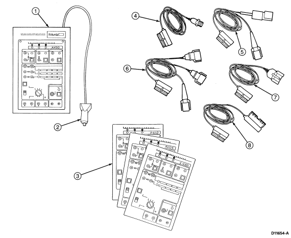
Transmission Tester/Overlays and Adapters

Item |
Part Number |
Description |
|
1
|
—
|
Transmission Tester
|
|
2
|
—
|
Power Cable
|
|
3
|
—
|
Overlay Cards
|
|
4
|
—
|
A4LD Adapter Cable
|
|
5
|
—
|
AODE Adapter Cable
|
|
6
|
—
|
AXODE Adapter Cable
|
|
7
|
—
|
E4OD Adapter Cable
|
|
8
|
—
|
Extender Cable
|
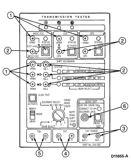
Tester Jacks

Item |
Part Number |
Description |
|
1
|
—
|
VPWR Pin Jacks (red): VPWR test points for solenoid circuits.
|
|
2
|
—
|
Solenoid Signal Line Pin Jacks (black) Signal line test points for
solenoid circuits.
|
|
3
|
—
|
B+ (red) and B- (black) Pin Jacks: Battery reference
points when measuring circuits for shorts.
|
|
4
|
—
|
TOT Pin Jacks: Test points for TOT sensor.
|
|
5
|
—
|
TSS or OSS Pin Jacks: Test points for TSS or OSS sensor.
|
|
6
|
—
|
Diode Test Jack: Connect banana plug end of test probe into this jack for
diode testing. Connect other end of test probe to solenoid signal pin jack
(with diode and check mark).
|
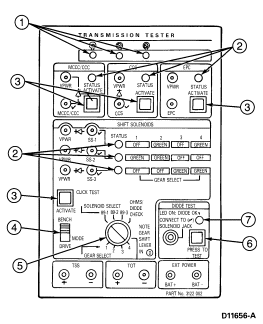
Tester LEDs and Controls

Item |
Part Number |
Description |
|
1
|
—
|
Overlay and Cable Correctly Installed LEDs: Only LEDs with
symbol and cable correctly matched.
|
|
2
|
—
|
Status LEDs: LED OFF when not activated by tester (solenoid
not activated, open circuit or signal line short to ground. LED GREEN when
activated by tester and current draw is correct. LED RED when activated by
tester and current draw is excessive (short to VPWR). All LEDs light orange
during on-board diagnostic.
|
|
3
|
—
|
Solenoid Activate Buttons: Energize respective solenoids
during click testing and activate selected circuits during DRIVE MODE testing.
|
|
4
|
—
|
Tester Mode Switch: Selects operating mode, either BENCH or
DRIVE.
|
|
5
|
—
|
Solenoid Select/Gear Select Knob: Has three functions. In
BENCH MODE: acts as shift solenoid selector for click testing. In DRIVE MODE:
acts as forward gear selector in place of vehicle's PCM-controlled shifting.
Hydraulic safety mechanisms and overrides are built into the transmission. In
OHMS/DIODE check: allows you to measure ohms and check for presence of a diode
on specific solenoids.
|
|
6
|
—
|
Diode Test Button: Activates DIODE TEST circuit.
|
|
7
|
—
|
Diode OK LED: With DIODE TEST BUTTON depressed, indicates
condition of diode. (LED ON: diode OK.)
|
Transmission Tester Instructions

The Transmission Tester allows a technician to operate the electrical
portion of the transmission independent of the vehicle electronics. The
Transmission Tester usage is divided into five steps:
- Preliminary Testing and Diagnosis
- Installing the Transmission Tester
- Static Testing — Vehicle OFF
- Dynamic Testing — Vehicle Running
- Removing the Transmission Tester and Clearing DTCs
Preliminary Testing and Diagnosis
Before any diagnostic testing is done on a vehicle some preliminary
checks must be performed, as outlined below. Be sure to write down your
findings, especially any DTCs found, for future reference.
- Check transmission fluid level and condition.
- Check for add-on items (phones, computers, CB radio, etc).
- Visually inspect wiring harness and connectors.
- Check for vehicle modifications.
- Verify that the shift linkage is properly adjusted.
- Verify customer concern.
- Upshift, Downshift, Coasting, Engagement, Noise/Vibration.
- Vehicle must be at a normal operating temperature.
- Perform vehicle EEC-IV On-Board Diagnostics.
- Record all DTCs.
- Repair all non-transmission codes.
Installing the Transmission Tester (Set Up Procedures)
Installing the Transmission Tester AT THE TRANSMISSION CONNECTOR allows
the separation of the vehicle electronics from the transmission electronics.
Disconnecting the normal vehicle electronics will in itself set additional
codes and cause firm shifts. (Disconnecting the transmission connector defaults
the transmission to maximum line pressure).
NOTE: During tester usage additional DTCs may be set. Therefore, it is
important that all codes are erased after repairs have been made. To verify
elimination of all codes rerun On-Board Diagnostics.
NOTE: A4LD transmission will not have firm shifts when using the tester. It
does not default to maximum line pressure.
NOTE: The following manuals should be available to assist in diagnosis of
electronically controlled transmissions:
- Powertrain Control/Emissions Diagnosis Manual (PC/ED) (formerly called the "H" manual)
- Service Manual
- Disconnect vehicle harness at transmission connector.
 CAUTION: Do not attempt to pry off connectors with a screwdriver. This will
damage the connector and could result in a transmission concern. If you have
transmission heat shields, remove them first. Always replace heat shields after
service.
- Turn tester solenoid select switch to the "OHMS/DIODE CHECK" position.
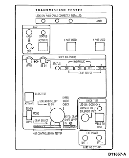
- Install A4LD overlay onto tester. Connect interface cable to transmission
tester and then to the transmission connector.
 CAUTION: Route all cables away from HEAT SOURCES.
- Plug transmission tester power supply plug into cigarette lighter
receptacle.
- At this time, all LEDs should illuminate for a short period and then
turn off. This is the tester internal circuit check.
- Bench/Drive switch set to "BENCH" mode.
Static Testing — Vehicle "OFF"
Static testing procedures allow for shop testing of the transmission in
the vehicle or on the bench. Completion of these tests prove out the
transmission electronically.
 CAUTION: For resistance checks, be sure that the tester solenoid select switch
is set to the "OHMS/DIODE CHECK" position or damage to the ohmmeter may result.
Resistance/Continuity Tests
- Refer to the appropriate Pinpoint Test to be performed based on the
On-Board Diagnostic Trouble Codes displayed.
- Using a digital volt-ohmmeter and the Transmission Tester perform the
Pinpoint Tests as required based on the On-Board Diagnostic Trouble Codes which
were displayed.
- Perform repairs as indicated by the Pinpoint Tests. Always retest and
road test vehicle after a repair.
Transmission Solenoids and Sensors Resistance Tests
Solenoids (SS 3-4/4-3, TCC)
- Set ohmmeter to 100-200 ohm range.
- Connect the positive lead of the ohmmeter to the appropriate VPWR jack
for the solenoid being tested.
- Connect the negative lead of the ohmmeter to the appropriate solenoid (SS
3-4/4-3, TCC).
- Record resistance.
- Refer to chart for values and transmission applications.
If out of range refer to the pinpoint tests.
Pinpoint Test A — (SS 3-4/4-3);
Pinpoint Test C — TCC
| SOLENOID |
SOLENOID RESISTANCE (ohms) |
SS 3-4/4-3
TCC |
26-40
26-40 |
Short to Ground and Solenoid Voltage Tests
NOTE: LED will turn GREEN when solenoid activates and turn OFF when deactivated.
LED will turn RED if an activated solenoid/harness
is shorted to B+.
LED will remain OFF if an activated
solenoid/harness is shorted to ground or no continuity.
- Tester Bench/Drive switch set to BENCH mode.
- Set voltmeter to 20 volt DC range.
- Connect voltmeter positive lead to the appropriate solenoid VPWR, connect
voltmeter negative lead to the appropriate solenoid.
- Using a VOM, check for voltage across each solenoid by activating the
solenoid switches. Depress the appropriate switch. The LED should illuminate,
the voltage should change and an audible click may be heard. If LED does not
illuminate, a short to ground condition exists.
NOTE: SS 3-4/4-3 and TCC solenoid click may or may not be audible.
- Observe and record values.
Solenoid Diode Test
- Only used on SOLENOIDS with a DIODE symbol.
- Using a test lead from a VOM, connect the test lead at the DIODE test jack
and to the appropriate solenoid signal jack (marked with check symbol).
- Depress diode switch and observe diode test LED. LED should illuminate
green if correct.
NOTE: A bad diode may cause PCM concerns.
Dynamic Testing — Vehicle Running
Dynamic testing is the final step in the Transmission Tester usage. It
allows the transmission to be proven out electronically and hydraulically.
Transmission Solenoid Cycling and Drive Test Procedures
Preliminary Set Up
- Bench/Drive switch set to DRIVE mode.
- Set rotate gear select switch to first gear position.
- Vehicle in PARK.
- Start vehicle.
Upshift/Downshift
NOTE: These tests should be performed on the road. If performed on the hoist
the technician may not feel all of the shifts when they are engaged.
LEDs will turn green when solenoids are activated and turn off
when deactivated. Refer to the appropriate overlay for the proper status/shift
sequence of the shift solenoids during upshift and downshifts.
SS 3-4/4-3 Upshift/Downshift
- Accelerate vehicle to 40 mph, allowing vehicle to upshift from
first to second and then into third gear.
Did the vehicle upshift from first to second and then into
third?
NOTE: These upshifts are hydraulically controlled.
- Accelerate vehicle to 45/55 mph and select fourth gear.
Did the vehicle upshift to fourth gear?
Did the 3-4/4-3 Shift solenoid activate/deactivate?
- Reverse the order to downshift.
Does the vehicle downshift for fourth to third, third to
second, and second to first?
Did the 3-4/4-3 Shift solenoid activate/deactivate?
Did the vehicle downshift hydraulically?
Torque Converter Clutch (TCC) Engagement
NOTE: This test should be performed on the road. If performed on the hoist the
technician may not feel the TCC engage.
 CAUTION: Do not depress TCC (CCO) switch with transmission in gear and the
vehicle at a stop. Damage to torque converter clutch may result.
- Accelerate vehicle to 55 mph and allow vehicle to upshift into third gear.
Hold speed steady and depress the TCC switch.
Does the converter engage? Does the engine RPM drop?
Did the TCC (CCO) solenoid activate/deactivate?
NOTE: Torque Converter Clutch (TCC) was formerly called Converter Clutch
Override (CCO).
Removing the Transmission Tester and Clearing DTCs
 CAUTION: Do not attempt to pry off connectors with a screwdriver. This will
damage the connector and could result in a transmission concern.
- Disconnect transmission tester from the transmission connector.
- Reinstall vehicle wiring harnesses. Verify connection by pulling up on the
harness.
- Reinstall all heat shields that were previously removed.
- Disconnect transmission tester power lead from vehicle.
- Erase all diagnostic trouble codes using the procedures in the Powertrain
Control/Emissions Diagnosis Manual. (Unlatch center button of STAR Tester while codes are being
displayed on a KOEO On-Board Diagnostic.)
- Rerun EEC-IV On-Board Diagnostics to receive a pass code (11 or 111).
- Verify that the customer concern has been eliminated.
 CAUTION: DTCs in continuous memory can be erased by disconnecting the battery
or by ungrounding the Self Test Input (STI) while the codes are being displayed
during the KOEO On-Board Diagnostics. This STI is ungrounded by disconnecting
the small Data Link connector or unlatching the STAR Tester button. Always
write down the DTCs to avoid losing information that can be used to diagnose
the customer's concern.


