A4LD NAAO Automatic Overdrive Transmission (Band and Clutch Application/Gear Ratio)
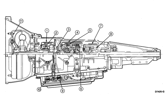
Band and Clutch Application/Gear Ratio Chart
Section 07-01A: Transmission, Automatic, A4LD | 1993 Mustang Workshop Manual |
Troubleshooting the automatic transmission is simplified by using the proven methods of diagnosis. One of the most important things to remember is that there is a definite procedure to follow. Do not try to short-cut or assume that someone else has done the critical checks or adjustments.
Refer to the Band and Clutch Application and Gear Ratio illustration to
assist in diagnosis.
A4LD NAAO Automatic Overdrive Transmission (Band and Clutch
Application/Gear Ratio)

Band and Clutch Application/Gear Ratio Chart
| Position | Function | 1 | 2 | 3 | 4 | 5 | 6 | 7 | 8 | 9 | 10 | 11 | Gear Ratio |
|---|---|---|---|---|---|---|---|---|---|---|---|---|---|
| P | Park | — | |||||||||||
| R | Reverse | A | H | A | A | 2.1:1 | |||||||
| N | Neutral | — | |||||||||||
| (D) | 1st | H | A | H | 2.47:1 | ||||||||
| (D) | 2nd | H | A | A | 1.47:1 | ||||||||
| (D) | 3rd | H | A | A | 1.0:1 | ||||||||
| (D) | 4th — Converter Clutch Above Approximately 48 km/h (30 mph) | A | A | A | E | P | P | 0.75:1 | |||||
| (D) | 4th — Converter Clutch Below Approximately 48 km/h (30 mph) | A | A | HO | 0.75:1 | ||||||||
| D | 1st | A | H | A | H | 2.47:1 | |||||||
| D | 2nd | A | H | A | A | 1.47:1 | |||||||
| D | 3rd — Converter Clutch Above Approximately 48 km/h (30 mph) | A | H | A | A | P | P | 1.0:l | |||||
| D | 3rd — Converter Clutch Below Approximately 48 km/h (30 mph) | A | H | A | A | HO | 1.0:1 | ||||||
| 2 | Manual 2nd | A | H | A | A | 1.47:1 | |||||||
| 1 | Manual 1st | A | H | A | A | H | 2.47:1 |
NOTES:
A = Applied
H = Holding
P = Processor Controlled
E =
Energized
HO = Hydraulically Over-Ridden
1 = Overdrive Band
2 =
Forward/Rev. Coast Clutch
3 = Front O.W.C.
4 = Int. Band
5 = High/Rev.
Clutch
6 = Forward Clutch
7 = Low/Rev. Band
8 = Rear O.W.C.
9 = 3-4
Solenoid
10 = Converter Clutch Solenoid
11 = Converter Clutch
Automatic Transmission Linkage Check
Accelerator Pedal Linkage and Operation
The linkage must be free and must return to idle when released. Refer to
Engine Service Manual, Section 10-02, for linkage adjustment.
Kickdown Cable Adjustment
Refer to Section 07-05 for Kickdown Cable Adjustment.
Manual Shift Cable
This is a critical adjustment. Be sure the (D) (overdrive) detent in the transmission corresponds exactly with the stop in the console or column insert plate. Hydraulic leakage at the manual valve can cause delay in engagements and/or slipping while operating if the cable is not properly adjusted. Refer to Adjustments in Section 07-05, for detailed manual shift cable adjustment procedures.
Transmission Fluid Leakage Checks
Check the speedometer cable connection at the transmission. Replace the rubber O-ring if necessary.
Leakage at the oil pan gasket often can be stopped by tightening the attaching bolts to the proper torque. If necessary, replace the gasket.
Check the fluid filler tube connection at the transmission case. Check filler tube O-ring seal for damage or omission. If leakage is found, install a new short oil inlet tube and O-ring seal, or clean the area and apply a sealer around the tube. The filler tube bracket should align properly and be attached to the transmission or engine locations.
Check the fluid lines and fittings between the transmission and the
cooler in the radiator tank for looseness, wear, or damage. If leakage is
found, tighten the fitting to the specified torque value (as shown in chart
below), or replace the damaged parts.
| Fitting Location | Nm | Ft-Lb |
|---|---|---|
| Radiator | 35-43 | 26-32 |
| Transmission | 35-43 | 26-32 |
| Fluid Line Nut | 27-35 | 20-26 |
Check the engine coolant in the radiator. If transmission fluid is present in the coolant, the cooler in the radiator is probably leaking.
The cooler can be further checked for leaks by disconnecting the lines from the cooler fittings and applying 345-517 kPa (50-75 psi) air pressure to the fittings. Remove the radiator cap to relieve the pressure buildup at the exterior of the oil cooler tank. If the cooler is leaking and/or will not hold pressure, the cooler must be replaced.
If leakage is found at the downshift control lever and the manual lever shaft, replace the seal.
Inspect the pipe plug on the left rear side of the transmission case. If the plug shows leakage, tighten the plug to specifications. If leakage continues, replace the plug.
Fluid leakage from the converter housing may be caused by engine oil leakage past the rear main bearing, or from oil galley plugs, or power steering fluid leakage from steering system. Be sure to determine the exact cause of the leak before starting service procedures.
Oil-soluble aniline or fluorescent dyes premixed at the rate of 2.5 ml (1/2 teaspoon) of dye powder to 0.23 liter (1/2-pint) of transmission fluid have proved helpful in locating the source of fluid leakage. Such dyes may be used to determine whether an engine oil or transmission fluid leak is present, or if the fluid in the oil cooler leaks into the engine coolant system. A black light must be used with the fluorescent dye solution.
Fluid Leakage in Converter Area
In diagnosing and correcting fluid leaks in the front pump and converter
area, use the following procedures to locate the exact cause of the leakage.
Leakage at the front of the transmission, evidenced by fluid around the
converter housing, may have several sources. By careful observation it is
possible, in many instances, to pinpoint the source of the leak before removing
the transmission from the vehicle. The paths which the fluid takes to reach the
bottom of the converter housing are shown.
Fluid Leakage Points, Converter Area
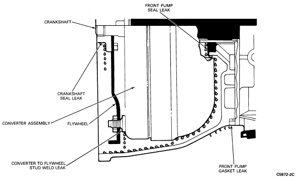
Engine oil leaks are sometimes improperly diagnosed as transmission front pump seal leaks. The following areas of possible leakage should also be checked to determine if engine oil leakage is causing the problem:
Converter Leakage Check
If welds on the torque converter indicate leakage, remove the converter and make the following check.
Assemble Rotunda 021-00054 Torque Converter Leak Tester or equivalent to
the converter as shown. Test the converter for leaks following the directions
supplied with the detector kit.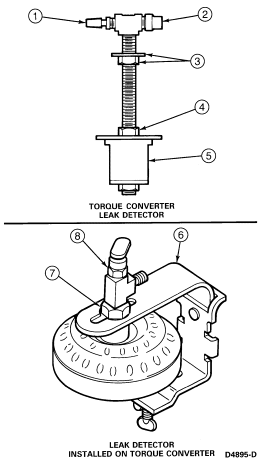
| Item | Part Number | Description |
|---|---|---|
| 1 | — | Pressurization Valve |
| 2 | — | Relief Valve |
| 3 | — | Top Fixture Nut and Washer |
| 4 | — | Plug Compressing Nut |
| 5 | — | Rubber Plug Body |
| 6 | — | Retaining Strap |
| 7 | — | Plug Compressing Nut |
| 8 | — | Top Fixture Nut |
Control Pressure Test
There are two methods of performing the control pressure test. One is to perform the test using the engine vacuum. The second method is to use a remote vacuum source such as the one provided by a distributor tester or a hand-operated vacuum pump.
Engine Vacuum Pressure
When the vacuum diaphragm unit is operating properly and the manual shift cable and downshift linkage is adjusted properly, all the transmission shifts (automatic and kickdown) should occur within the road speed limits listed in the Technical Service Bulletin, Special Specifications Issue.
If the shifts do not occur within limits, or the transmission slips during the shift point test, use the following procedure to determine whether the engine, transmission, linkage, vacuum diaphragm unit, or valve body is causing the condition.
Engine Vacuum Procedure
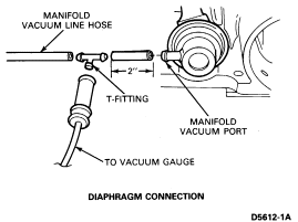
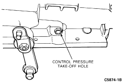
Refer to the two control pressure diagnostic guides to show what components are inoperative when the control pressure test is not within specifications. Do not proceed with the main diagnosis guide until you have made any repairs, as required, and the control pressure is within specifications as listed in the Performance Specifications Book or Special Specifications Issue of the Technical Service Bulletin.
Vacuum Pump Method
Disconnect and temporarily plug the vacuum line going to the vacuum diaphragm unit. Install an adjustable vacuum source. Apply both the parking and service brakes. Start the engine and vacuum pump. Set the vacuum at 15-inches, read and record the control pressure in all selector positions. Run the engine up to 1000 rpm, and reduce the vacuum to 10-inches. Read and record the control pressure in (D), D-2 and -1. Keep the engine at 1000 rpm and reduce the vacuum to one inch. Read and record the control pressure in (D) , D-1, -2 and R.
Refer to the two control pressure diagnosis charts to show what
components are inoperative when the control pressure test is not within
specification. Do not proceed with the main diagnosis chart until serviced as
required, and the control pressure is within specification as listed in the
Performance Specifications Book or Special Specifications Issue of the
Technical Service Bulletin.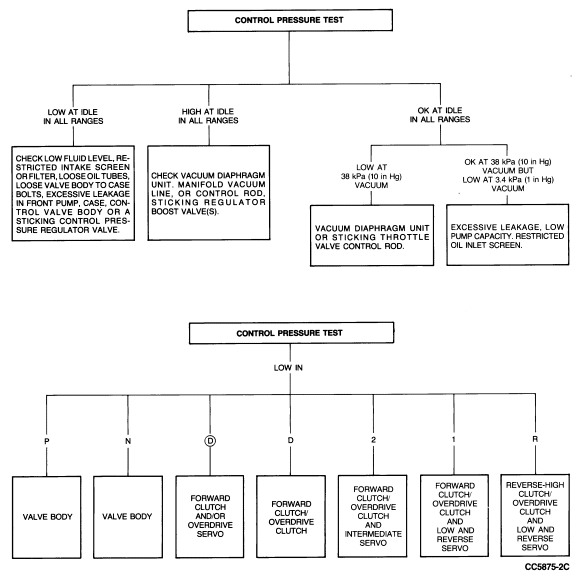
Vacuum Supply Test
The vacuum supply to the vacuum diaphragm unit and the diaphragm itself must be checked. To check the supply, disconnect the vacuum line at the diaphragm unit and connect it to a vacuum gauge. With the engine idling, the gauge must have a steady acceptable vacuum reading for the altitude at which the test is being performed. If the vacuum reading is low, check for a vacuum leak or poor engine vacuum. If the vacuum reading is OK, rapidly accelerate the engine momentarily. The vacuum reading must drop rapidly at acceleration and return immediately upon release of the accelerator pedal. If the vacuum reading does not change or changes slowly, the transmission vacuum line is plugged, restricted or connected to a reservoir supply. Correct as required.
Vacuum Diaphragm Test, On-Vehicle
To check the vacuum diaphragm unit, disconnect the vacuum line at the
diaphragm and connect a hand vacuum pump such as Rotunda 021-00014 or
equivalent. Apply 18 inches of vacuum. If the vacuum reading drops, the
diaphragm is leaking, and it must be replaced. Also, if there is transmission
fluid present in the vacuum side of the diaphragm or in the vacuum hose, the
diaphragm is leaking and must be replaced.
Testing Vacuum Diaphragm
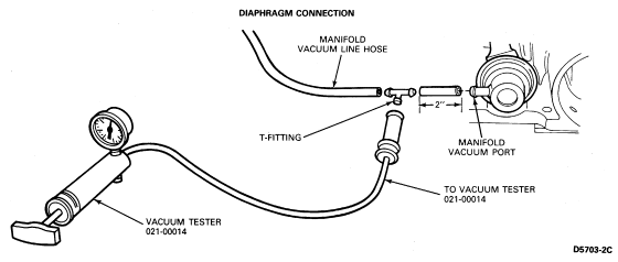
Vacuum Diaphragm Test, Off-Vehicle
To check the vacuum unit for diaphragm leakage, remove the unit from the transmission. Use Vacuum Tester Rotunda Number 021-00014 or equivalent. Adjust the tester until the vacuum gauge reads 18 inches with the end of the vacuum hose blocked off.
Connect the vacuum hose to the manifold vacuum port as shown. If the
gauge still reads 18 inches, the vacuum unit diaphragm is not leaking. A second
leakage check can be made as the hose is removed from the transmission vacuum
unit. Hold a finger over the end of the control rod. When the hose is removed
the internal spring of the vacuum unit should push the control rod outward. If
the vacuum diaphragm needs replacing, install a new unit that has been released
for service. Vacuum diaphragm assembly identification is given at end of this
section.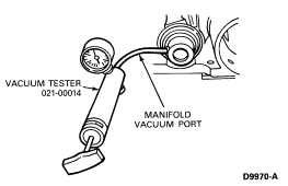
Torque Converter Clutch Test
NOTE: Engine coolant temperature must be above 53°C (128°F) and below 116°C (240° F). This temperature can be obtained after approximately 15 minutes of highway driving. Since most torque converter clutch shifts are difficult to feel (much less noticeable than a 1-2 or 2-3 upshift) a tachometer and/or vacuum gauge must be connected to the engine.
To check the torque converter clutch for engagement/disengagement, drive the vehicle at approximately 80 km/h (50 mph) and, while maintaining this speed, tap the brake pedal with the left foot. The engine rpm and vacuum should increase when the clutch disengages, with light brake pedal application, and decrease when the pedal is released and the clutch engages. If the torque converter clutch does not engage, see Diagnosis portion of this section.
Stall Test
The stall test checks converter one-way clutch operation and
installation, the holding ability of the forward clutch, reverse clutch, the
low-reverse bands, the planetary one-way clutch and engine performance. 
The test should be done only with the engine coolant and transmission fluid at proper levels and at operating temperature.
Apply the service and parking brakes firmly for each stall test.
 CAUTION: Holding at stall speed for longer than 5 seconds could result in
damage to internal transmission components.
 CAUTION: If the engine speed recorded by the tachometer exceeds the maximum
limits given in Specifications, release the accelerator pedal immediately,
because clutch or band slippage is indicated.
Governor Check
The governor can be checked at the same time as the Control Pressure Test is performed and in the same manner.
Raise the vehicle with an axle or frame hoist so that the rear wheels are clear of the floor. Disconnect and plug the vacuum line to the vacuum diaphragm unit. Connect the line from the adjustable vacuum source to the vacuum diaphragm unit.
 CAUTION: Never exceed 96 km/h (60 mph) speedometer speed.
Place the transmission in (D) or D range with no load on the engine, and apply 10 inches of vacuum to the vacuum diaphragm unit. Increase the speed slowly and watch the speedometer. Check the km/h (mph) at which the control pressure cutback occurs. It should occur between 13-19 km/h (5-15 mph). Decrease the vacuum at the vacuum diaphragm to 0-2 inches. Control pressure cutback should occur between 18-28 km/h (7-20 mph).
NOTE: After each test, move the selector to N (neutral) and run the engine at 1000 rpm for about 15 seconds to cool the transmission.
The governor is good if the cutback occurs within these specifications. If the cutback does not occur within specifications, check shift speed to verify that it is the governor and not a stuck cutback valve, then service or replace the governor.
Transmission Fluid Cooler Flow Check
The shift cable, linkage, fluid level and control pressure must be within specifications before performing this flow check.
Remove the transmission dipstick from the filler tube. Place a funnel in the transmission filler tube. Raise the vehicle; remove the cooler return line from its fitting in the case. Attach a hose to the cooler return line and fasten the free end of the hose in the funnel installed in the filler tube.
Start the engine and set idle speed at 1000 rpm with the transmission in N (neutral).
Observe the fluid flow at the funnel. When the flow is solid (air bleeding has been completed), the flow should be liberal. If there is not a liberal flow at 1000 rpm in N (neutral), low pump capacity, main circuit system leakage, stuck converter charge relief valve or cooler system restriction is indicated.
To separate transmission trouble from cooler system trouble, observe the flow at the transmission case converter-out fitting.
Shift Point Checks
Road Test
This check will determine if the electronics, governor and shift control valves are functioning properly.
Check the light throttle upshifts with selector in overdrive range (approximately 10 inches Hg vacuum). The transmission should start in first gear, shift to second gear, shift to third gear, shift to fourth gear (overdrive) and then lock the torque converter clutch. The converter lockup is often difficult to feel, therefore a vacuum gauge and tachometer should be used to determine lockup shift points. Refer to the Ford Performance Specifications Book or the Special Specifications Issue of the Technical Service Bulletin for actual shift point vehicle speed.
When the selector lever is in D position, the transmission will make all automatic upshifts except the 3-4.
When the selector is at 2 (second), the transmission can operate only in second gear.
With the transmission in third gear and road speed over 72 km/h (45 mph) the transmission should shift to second gear when the selector lever is moved from D (drive) or 2 (second) to 1 (first). This check will determine if the governor pressure and shift control valves are functioning properly.
If the vehicle is traveling at approximately 72 km/h (45 mph) and the selector lever is moved from (D) (overdrive) to 1 or D to 1 (closed throttle), the transmission will immediately downshift to second gear. As road speed drops below 48 km/h (30 mph) the transmission will downshift to first gear.
For a coastdown from approximately 72 km/h (45 mph) with the transmission in (D) position and at closed throttle, the downshift sequence is as follows: torque converter clutch unlocks electronically when the accelerator pedal is released, as vehicle speed drops, 4-3, 3-2 and finally 2-1 downshifts happen.
In Shop
A shift test can be performed in the shop to check shift valve operation, governor circuits, shift delay pressures, throttle boost and downshift valve action.
Raise the vehicle with an axle or frame hoist so that the rear wheels are clear of the floor. Disconnect and plug the vacuum line from the engine to the diaphragm. Connect the line from the adjustable vacuum source to the vacuum diaphragm unit.
 CAUTION: Never exceed 96 km/h (60 mph) speedometer speed.
If the shift points are not within specification, perform a governor check to isolate the problem.
NOTE: After each test, move the selector lever to neutral and run the engine at 1000 rpm for about 15 seconds to cool the transmission.
NOTE: After each test, move the selector lever to neutral and run the engine at 1000 rpm for about 15 seconds to cool the transmission.
Shift speed specifications can be found in the Performance Specifications Book or the Special Specifications Issue of the Technical Service Bulletin.
Air Pressure Checks
NOTE: A4LD Transmission Test Plate (T86L-7006-A) may be used with a gasket to check bands and clutches.
A no drive condition can exist, even with correct transmission fluid pressure, because of inoperative clutches or bands. On automatic transmissions, an erratic shift can be caused by a stuck governor valve. The inoperative units can be located through a series of checks by substituting air pressure for fluid pressure to determine the locations of the malfunction.
When the selector lever is at 2 (manual second), a no drive condition may be caused by an inoperative forward clutch. A no drive condition at D (drive) may be caused by an inoperative forward clutch or one-way clutch. When there is no drive in 1 (manual low) the difficulty could be caused by improper functioning of the forward clutch or simultaneous malfunction of the low-reverse band and the one-way clutch. Failure to drive in R (reverse) could be caused by a malfunction of the reverse-high clutch or low-reverse band.
To make the air pressure checks, loosen the oil pan bolts and lower one
edge to drain the transmission fluid. Remove the oil pan and the control valve
body assembly. The inoperative clutches or bands can be located by introducing
air pressure using Air Nozzle Assembly TOOL-7000-DE and Rubber Tip TOOL-7000-DD
into the various transmission case passages.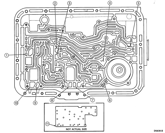
| Item | Part Number | Description |
|---|---|---|
| 1 | — | Overdrive Clutch Apply |
| 2 | — | Reverse and High Clutch Apply |
| 3 | — | Forward Clutch Apply |
| 4 | — | Low and Reverse Servo Release |
| 5 | — | Forward Clutch Feed to Governor |
| 6 | — | Low and Reverse Servo Apply |
| 7 | — | Intermediate Servo Release |
| 8 | — | Intermediate Servo Apply |
| 9 | — | Overdrive Servo Release |
| 10 | — | Overdrive Servo Apply |
| 11 | T86L-7006-A | A4LD Transmission Test Plate |
Forward Clutch
Apply air pressure to the transmission case forward clutch passages. A dull thud can be heard when the clutch piston is applied. If no noise is heard, place the fingertips on the input shell and again apply air pressure to the forward or front clutch passage. Movement of the piston can be felt as the clutch is applied.
Governor
Apply air pressure to the forward clutch feed to governor passage and listen for a sharp clicking or whistling noise. The noise indicates governor valve movement.
Overdrive Servo
Hold the air nozzle in the overdrive servo apply passage. Operation of the servo is indicated by a tightening of the overdrive band around the overdrive drum. Continue to apply air pressure to the servo apply passage and introduce air pressure into the overdrive servo release passage. The overdrive servo should stroke off releasing the overdrive band.
Overdrive Clutch (Applied in D, 2, 1 and R Ranges)
Apply air pressure to the overdrive clutch feed passage. A dull thud indicates that the overdrive clutch piston has moved to the applied position.
Reverse-High Clutch
Apply air pressure to the reverse-high clutch. A dull thud indicates that the reverse-high clutch piston has moved to the applied position. If no noise is heard, place the finger tips on the clutch drum and again apply air pressure to detect movement of the piston.
Intermediate Servo
Hold the air nozzle in the intermediate servo apply passages. Operation of the servo is indicated by a tightening of the intermediate band around the drum. Continue to apply air pressure to the servo apply passage, and introduce air pressure into the intermediate servo release passage. The intermediate servo should release the band against the apply pressure.
Low-Reverse Servo
Apply air pressure to the low-reverse servo. The low-reverse band should tighten around the drum if the servo is operating properly.
Air Pressure Check Diagnosis
If the servos do not operate, disassemble, clean, and inspect them to locate the source of the trouble.
If air pressure applied to either of the clutch passages fails to operate a clutch or operates both clutches at once, remove, and with air pressure, check the fluid passages in the case and front pump to detect obstructions.
Torque Converter Clutch Operation
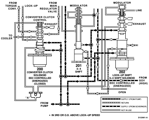
In the A4LD transmission, torque converter clutch upshifts and downshifts are scheduled electronically, but are overridden hydraulically under 30 mph. The torque converter clutch is inhibited from engaging during the following driving modes:
During the above driving modes no current flows through the solenoid. To describe the operation of the system refer to the following illustrations. When the torque converter clutch shuttle valve is resting on the plug, line pressure is directed through the shuttle valve and to the torque converter in a flow path that pushes the lockup piston off. Refer to Torque Converter Clutch Disengaged schematic. When line pressure on the spring end of the torque converter clutch shuttle valve is exhausted, line pressure on the plug end of the valve forces the valve to move and compress the spring. Line pressure is now directed through the shuttle valve to the converter in a flow path that pushes the piston on.
Above 30 mph governor pressure causes the torque converter clutch shift valve to upshift, exhausting the LUH circuit allowing the TCC solenoid to operate the torque converter clutch shuttle valve as follows: When torque converter clutch engagement is scheduled, the TCC is energized and the lock-up inhibit circuit is exhausted. This allows line pressure on the plug end of the valve to push the torque converter clutch shuttle valve into the upshift position. When the valve is upshifted, the torque converter clutch engages.
The torque converter clutch is disengaged electronically during some driving conditions. The following illustrations describe the solenoid functions and unique conditions.
With the vehicle at speeds below 48 km/h (30 mph), the converter clutch
is disengaged by both hydraulic and electronic direction. Low governor feed
pressure and the Bore No. 200 solenoid, in an open state, are directing fluid
to the converter clutch control valve to disengage the converter clutch.
Converter Clutch Electrically and Hydraulically inhibited (Unlocked)
Low Governor
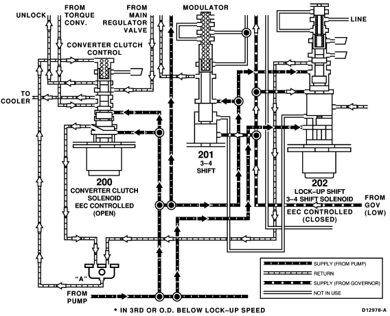
When the converter clutch is electrically inhibited, it lists the
controlled conditions which will continue to keep the converter clutch
disengaged electronically even when governor feed pressure is high.
Converter Clutch Electrically Inhibited (Unlocked) High Governor
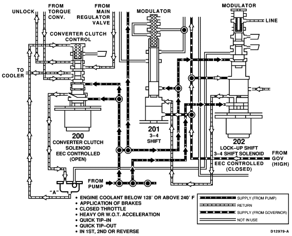
With a condition where the Bore No. 200 solenoid remains energized
(closed) or seized (closed) below 48 km/h (30 mph), the converter clutch is
disengaged by hydraulic override, to prevent engine stalling.
Lock-Up Hydraulically (Unlocked) Over-Ridden Under 30 MPH

With the vehicle at speeds above 48 km/h (30 mph), the torque converter
clutch will engage in D-3 or O.D.-4 if none of the conditions shown in the
following illustration are present.
Converter Clutch (Locked)
