Section 03-01B: Engine, 5.0L HO and 5.0L Cobra | 1993 Mustang Workshop Manual |
DISASSEMBLY AND ASSEMBLY
 CAUTION: Do not oil threads that require oil resistant or water resistant sealer.
When installing nuts or bolts, oil the threads with light weight engine
oil.
Refer to Section 03-00 for Cleaning and Inspection procedures.
Pistons and Connecting Rods
Tools Required:
- Piston Pin Remover/Replacer T68P-6135-A
Disassembly
- Remove the bearing inserts from the connecting rod and cap.
- Mark the pistons to ensure assembly with the same rod and installation in
the same cylinders from which they were removed.
- Remove the piston rings. Using an Arbor Press and Piston Pin
Remover/Replacer T68P-6135-A, press the piston pin from the piston and
connecting rod.
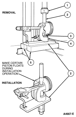
| Item |
Part Number |
Description |
|
1
|
Ś
|
Press Ram
|
|
2
|
T68P-6135-A
|
Piston Remover/Replacer
|
|
3
|
6135
|
Piston Pin
|
|
4
|
Ś
|
Reveiving Tube
|
|
5
|
Ś
|
Press Plates
|
Assembly
The piston, connecting rod and related parts are shown. Check the fit of a new piston in the cylinder bore before
assembling the piston and piston pin to the connecting rod.
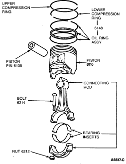
The piston pin bore of a connecting rod and the diameter of the piston
pin must be within specification. Refer to Specifications.
- Apply a light coat of engine oil XO-10W30-QSP (ESE-M2C153-E) or equivalent
to all parts. Assemble the piston to the connecting rod with the
cylinder number side of the connecting rod and the indentation notch in the
piston positioned as shown.
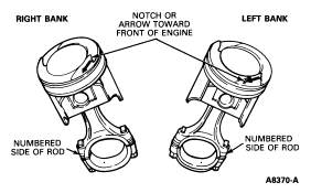
On replacement connecting rods, install the large chamfered
side of the connecting rod bearing bore towards the crankshaft cheek; facing
towards front of engine on RH bank rods, and facing towards rear of engine on
LH bank rods.
- Start the piston pin in the piston and connecting rod. (This may require a
very light tap with a mallet). Using an arbor press, press the piston pin
through the piston and connecting rod until the pin is centered in the piston.
- Check the end gap of all piston rings. Refer to Section 03-00. It must be
within specification. Follow the instructions contained on the piston ring
package and install the piston rings.
CAUTION: If the lower lands have high steps, the piston should be replaced.
- Check the ring side clearance of the compression rings with a feeler gauge
inserted between the ring and its lower land. Refer to Section 03-00. The gauge
should slide freely around the entire ring circumference without binding. Any
wear that occurs will form a step at the inner portion of the lower land.
- Ensure bearing inserts and the bearing bore in the connecting rod and cap
are clean. Foreign material under the inserts will distort the bearing and
cause a failure. Install the bearing inserts in the connecting rod and cap with
the tangs fitting in the slots provided.