Electronic Search Radio (ESR)
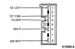
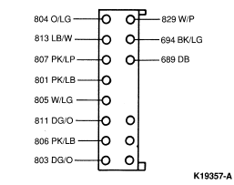
Radio Connector
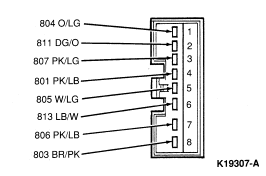
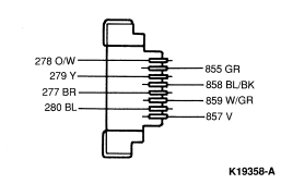
Speaker Connector
Electronic Stereo Cassette (ESC Lo-Power and CDR)
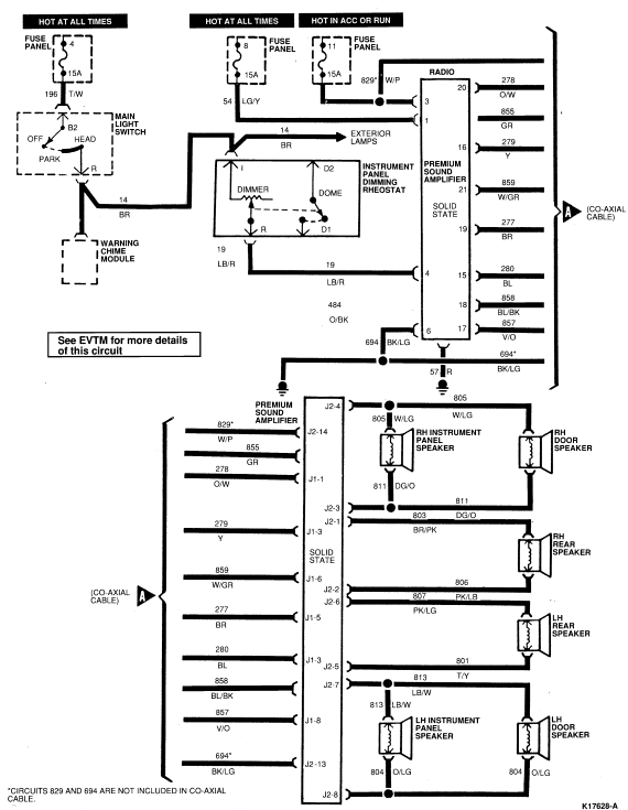
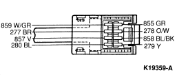
Amplifier
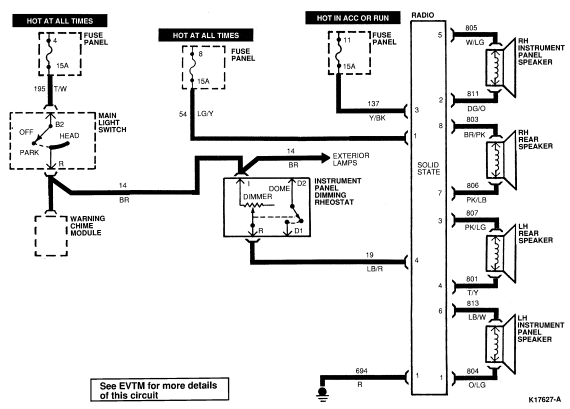
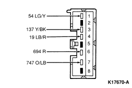
Radio
Circuit Description Chart
Section 15-00: Audio Systems—Service | 1993 Mustang Workshop Manual |
Tools Required:
Refer to the wiring diagrams and the diagnosis Charts to isolate radio
concerns.
Electronic Search Radio (ESR)
Radio Connector
Speaker Connector
Electronic Stereo Cassette (ESC Lo-Power and CDR)
Amplifier
Radio
Circuit Description Chart
| Circuit No. | Description | Gauge | Color | Stripe |
|---|---|---|---|---|
| 829 | Input to P.S.A. | 14 | W/P | X |
| 694 | Amplifier Power Return | 14 | BK/LG | X |
| 813 | Speaker Return LH Front Speaker | 18 | LB/W | X |
| 811 | Speaker Return RH Front Speaker | 18 | DG/O | X |
| 822 | Speaker Voice Coil Feed | 18 | BK/G | X |
| 807 | Speaker Voice Coil Feed Rear (LH Channel) | 18 | PK/LP | X |
| 806 | Speaker Voice Coil Feed Rear (RH Channel) | 18 | PK/LB | X |
| 805 | Speaker Voice Coil Feed Front (RH Channel) | 18 | W/LG | X |
| 804 | Speaker Voice Coil Feed Front (LH Channel) | 18 | O/LG | X |
| 803 | Speaker Voice Coil Return Rear (RH Channel) | 18 | DG/O | X |
| 801 | Speaker Voice Coil Return Rear (LH Channel) | 18 | PK/LB | X |
| 57 | Ground | 20 | BK | |
| 859 | Speaker Voice Coil Return | 18 | W/P | X |
| 137 | Radio and Antenna Feed | 18 | Y/BK | X |
| 54 | Memory Feed | 18 | LG/Y | X |
| 19 | Instrument Panel Lamps Feed | 18 | LB/R | X |
| 278 | RH RR + Input | 24 | O/W | X |
| 279 | RH FR + Input | 24 | Y | |
| 277 | LH RR + Input | 24 | BR | |
| 280 | LH FR + Input | 24 | BL | |
| 855 | RH RR - Input | 24 | GR | |
| 858 | RH FR - Input | 24 | BL/BK | X |
| 859 | LH RR - Input | 24 | W/GR | X |
| 857 | LH FR - Input | 24 | Y/O | |
| 689 | Mute | 18 | DB |
NOTE: The capacitor mounting points are used to complete the electrical circuit and must be mounted securely to clean surfaces.
NOTE: All surfaces used for grounding must be clean to ensure good electrical contact. Remove any dirt, rust, grease, paint, etc.
NOTE: All surfaces used for grounding must be clean to ensure good electrical contact. Remove any dirt, rust, grease, paint, etc.
NOTE: For a repeated customer complaint perform the above test while driving on rough road conditions to isolate the system exhibiting an intermittent short circuit condition.
NOTE: Use premium sound diagnostic chart to service if vehicle is so equipped.
NOTE: In EPC installations neither wire to the speaker can be grounded. Grounding of either wire will cause distortion.