Section 12-03A: Air Conditioning SystemŚManual A/C-Heater | 1994 Mustang Workshop Manual |
Removal and Installation
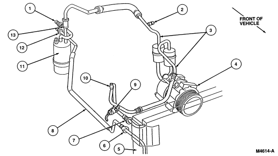
| Item | Part Number | Description |
|---|---|---|
| 1 | Ś | From Evaporator Core Outlet Tube |
| 2 | Ś | Low Side Service Valve Body (Part of 19D734) |
| 3 | 19D734 | A/C Manifold and Tube |
| 4 | 19703 | A/C Compressor |
| 5 | 19712 | A/C Condenser Core |
| 6 | Ś | To A/C Evaporator Core |
| 7 | Ś | From A/C Compressor |
| 8 | 19835 | Condenser to Evaporator Tube |
| 9 | 19D594 | A/C Pressure Cut-Off Switch |
| 10 | Ś | High Side Service Valve Body (Part of 19D734) |
| 11 | 19C913 | Suction Accumulator/Drier |
| 12 | Ś | To A/C Evaporator Core |
| 13 | Ś | Suction Hose From Accumulator (Part of 19C836) |
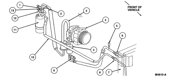
| Item | Part Number | Description |
|---|---|---|
| 1 | Ś | From Evaporator Core Outlet Tube |
| 2 | Ś | Low Side Service Valve Body (Part of 19D734) |
| 3 | 19D734 | A/C Manifold and Tube |
| 4 | 19703 | A/C Compressor |
| 5 | Ś | High Side Service Valve Body (Part of 19D734) |
| 6 | Ś | From A/C Compressor |
| 7 | 19712 | A/C Condenser Core |
| 8 | Ś | To A/C Evaporator Expansion Valve Mounting Bracket |
| 9 | 19D594 | A/C Pressure Cut-Off Switch |
| 10 | 19835 | Condenser to Evaporator Tube |
| 11 | 19C913 | Suction Accumulator/Drier |
| 12 | Ś | To A/C Evaporator Core |
| 13 | Ś | Suction Hose From Accumulator (Part of 19C836) |
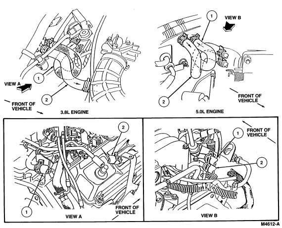
Heater Water Hoses
Removal
Installation
| Item | Part Number | Description |
|---|---|---|
| 1 | 18472 |
3.8L Inlet Heater Water Hose 5.0L Inlet Heater Water Hose |
| 2 | 18472 |
3.8L Outlet Heater Water Hose 5.0L Outlet Heater Water Hose |