Section 14-00: Battery and Charging System—Service | 1994 Mustang Workshop Manual |
DIAGNOSIS AND TESTING
Component Tests
Battery
Maintenance-Free Batteries
Read the battery open circuit terminal voltage with a digital voltmeter
such as Rotunda Digital Volt-Ohmmeter 007-00001 or equivalent, capable of
reading 1/100 volt. If open circuit voltage of battery (10653)
is below 12.4 volts and the battery
has passed the capacity test, charge the battery
.
NOTE: Whenever possible, test and charge battery
at or near room temperature.
- Use a high rate discharge tester with a variable rate control or a fused
rate tester with meter compensation for different battery electrical sizes.
Follow instructions supplied with tester for the battery capacity test.
- Recommended discharge rate at 27°C (80°
F): one-half of the cold cranking amps.
| Cold Cranking Amps |
Discharge Rate Amps |
| 650 |
325 |
| 540 |
270 |
- Voltage readings at 15 seconds for good battery
(Battery Capacity Test).
| Approximate Battery Temperature |
Minimum Load Voltage |
| 27°C(80°F) and above |
9.6 |
| 21°C(70°F) |
9.6 |
| 16°C(60°F) |
9.5 |
| 10°C(50°F) |
9.4 |
| 4°C(40°F) |
9.3 |
| -1°C(30°F) |
9.1 |
| -7°C(20°F) |
8.9 |
| -12°C(10°F) |
8.7 |
| -18°C(0°F) |
8.5 |
- Wait two minutes and check the Open Circuit Voltage (OCV).
- Measure OCV with a digital voltmeter capable of reading 1/100 volt.
Drain Test
Check for current drains on the battery
in excess of 100 milliamps with all the electrical
accessories off and the vehicle at rest. Current drains can be tested one of
three ways:
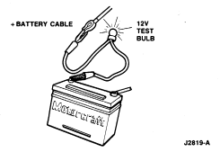
- Connect a 12-volt test lamp in series with battery positive terminal. If
lamp glows, then a drain exists.
- Use an in-line ammeter between the battery positive or negative post and
its respective cable.
- Use a clamp-on current probe to the battery positive or negative cable.
Make sure that the probe is properly calibrated to prevent false readings.

Typically, a drain of approximately one amp can be attributed to an
engine compartment lamp, glove compartment lamp, or luggage compartment lamp
staying on continually. Other component failures or wiring shorts may be
located by selectively pulling fuses or disconnecting fuse links to pinpoint
the location of the current drain. When the current drain is found, the test
lamp will go out or the meter reading will fall to an acceptable level. If the
short is still not located, after checking all the fuses and fuse links, the
drain may be due to the generator (GEN) (10346)
/generator regulator (10316). Disconnect the generator output wire from the output stud and the
generator regulator connector. If this eliminates the drain, check the charging
system to locate the concern.
NOTE: A voltmeter is sometimes used for this test but it will react to a very
small normal drain caused by "always-on" electronic systems such as starter
interlock, anti-theft alarm, illuminated entry, etc, which cause no concern.
The test lamp shows only drains which are large enough to cause a concern.
Battery Capacity Testing
With Clamp On DC Ammeter
Test Procedure
- Turn the ignition switch (11572)
to the OFF position and make sure there are no
electrical loads. After determining that the engine compartment lamp is turning
off properly, disconnect the lamp.
- Clamp the meter clip securely around positive or negative battery cable
(all cables if two or more lead to post).
NOTE: Do not start vehicle with clip on cable.
Test Conclusion
The current reading (current drain) should be less than 0.05 amp. If it
exceeds 0.05 it indicates a constant current drain which could cause a
discharged battery
. Possible sources of current drain are vehicle lamps
(engine compartment, glove compartment, luggage compartment, etc.) that do not
shut off properly.
If the drain is not caused by a vehicle lamp, remove fuses from the fuse
panel, one at a time, until the cause of the drain is located. If drain is
still undetermined, remove fusible links one at a time at the power
distribution box contained within the headlamp dash panel junction wire (14290)
to find the problem circuit.
With Voltmeter
This test requires a digital volt-ohmmeter with an appropriate low
voltage scale such as Rotunda Digital Volt-Ohmmeter 007-00001 or equivalent.
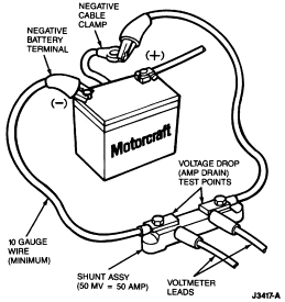
The meter must read within 0.01 millivolt. Also required is a shunt assembly
similar to that shown in the illustration.
Test Procedure
- Turn ignition switch
to the OFF position and make sure there are no
electrical loads. After determining the engine compartment lamp is turning off
properly, disconnect the lamp.
- Check battery voltage. If voltage is under 11.5 volts, charge the battery
to above 11.5 volts.
- Disconnect battery ground cable (14301)
.
NOTE: When the battery
is disconnected and reconnected, some abnormal drive symptoms may occur
while the powertrain control module (PCM) (12A650)
relearns its adaptive strategy. The vehicle may need to be driven 10
miles or more to relearn the strategy.
- Connect shunt assembly as shown.
 CAUTION: Do not crank the engine, it could destroy the shunt. Also do not use
the shunt to measure starting currents.
- Set volt-ohmmeter to 200 or 300 mv scale for an accurate reading (must be
within 0.01 millivolt).
- Connect meter leads to shunt as shown. With this size shunt (50 mv = 50
amps) and meter, a direct current drain measurement can be made.

Test Conclusion
The current reading (current drain) should be less than 0.05 amp. If the
reading is between 0.2 and 0.9 amp, a possible drain may be a vehicle lamp
(glove compartment, engine compartment, luggage compartment, etc.) that does
not turn off. If the cause of the drain is not a lamp, remove the fuses from
the fuse panel one at a time until the cause of the drain is located. If drain
is still undetermined, remove fuses one at a time at the power distribution box
to find the problem circuit.
Electronic Drains Which Shut Off When the Battery Cable is
Disconnected
- Repeat Steps 1 through 5 of the Battery Capacity Test with Voltmeter.
- Without starting engine, turn ignition switch
to the RUN position for a moment and then OFF. If
applicable, wait one minute for the illuminated entry lamps to turn off.
- Connect voltmeter and read voltage.
Test Conclusion
The current reading (current drain) should be less than 0.05 amp. If it
exceeds 0.05 after a few minutes, and if this drain did not show in previous
tests, the drain is most likely caused by a malfunctioning electronic
component. As in previous tests, remove fuses in power distribution box one at
a time to locate the problem circuit.
Generator On-Vehicle Tests
Troubleshooting or diagnosis is required before actual service can be
made in the electrical system. Even where an obvious condition makes
replacement of a component necessary, find out why the component failed. When a
condition is diagnosed correctly, unnecessary service is prevented, the time
the vehicle is out of service will be decreased, and the condition will be
properly corrected the first time.
NOTE: Refer to the Rotunda VAT-40 test procedure manual for complete directions
on checking out the charging system.
In order to check the charging system, the use of Rotunda Starting and
Charging Tester (VAT-40) 078-00005 or equivalent tester is suggested.
When performing charging system tests, turn OFF all lamps and electrical
components. Place transmission in NEUTRAL and apply parking brake.
 CAUTION: Do not make jumper wire connections except as directed. To do so may
damage generator regulator
.
NOTE: Battery posts and cable clamps must be clean and tight to
ensure accurate meter indications.
Load Test
- Switch the Rotunda Starting and Charging Tester (VAT-40) 078-00005 or
equivalent to the ammeter function.
- Connect the positive and negative leads of the Rotunda Starting and
Charging Tester (VAT-40) 078-00005 or equivalent to the battery
.
- Connect the current probe to the generator B+ output lead, Circuit 38
(BK/O).
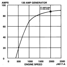
- With the engine running at 2000 rpm, adjust the Rotunda Starting and
Charging Tester (VAT-40) 078-00005 or equivalent load bank to determine the
output of the generator
. Generator output should be greater than the graph
shown below. If not, refer to the Symptom Chart in this Section for diagnostic
procedures.

No-Load Test
- Switch the Rotunda Starting and Charging Tester (VAT-40) 078-00005 or
equivalent to the voltmeter function.
- Connect the voltmeter positive lead to the generator B+ terminal and the
negative lead to ground.
- Turn all electrical accessories OFF.
- With the engine running at 2000 rpm, check the generator output voltage.
The voltage should be between 13.0 and 15.0 volts. If not, refer to the Symptom Chart in this Section for diagnostic procedures.
Generator Bench Tests
NOTE: The integral rear mount regulator—internal fan type generator
is serviced as an assembly only.
Replace generator
as required after performing Generator On-Vehicle
Tests. Refer to Section 14-02 for Removal and Installation procedures.

 CAUTION: Do not crank the engine, it could destroy the shunt. Also do not use
the shunt to measure starting currents.
