Section 11-04: Steering Column | 1994 Mustang Workshop Manual |
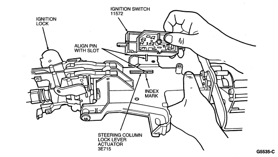
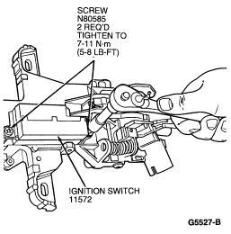
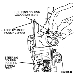
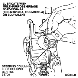
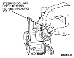
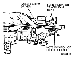
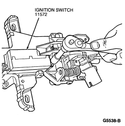
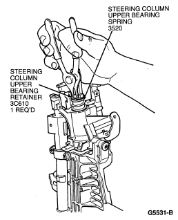
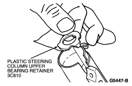
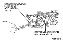
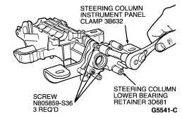
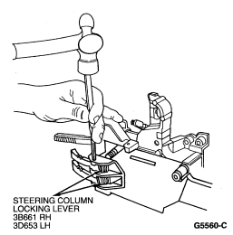
Disassembly
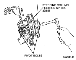
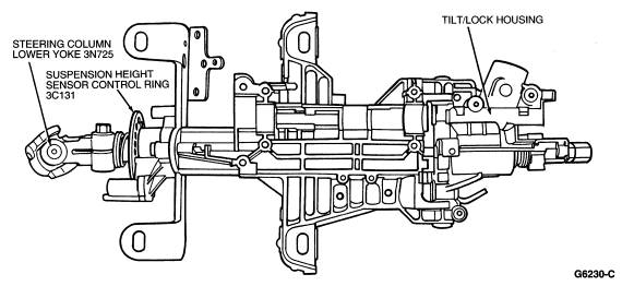
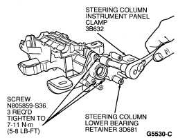
Assembly
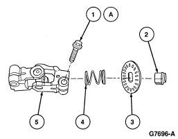
| Item | Part Number | Description |
|---|---|---|
| 1A | N803942 | Bolt |
| 2 | 3L539 | Steering Column Upper Bearing Tolerance Ring |
| 3 | 3C131 | Suspension Height Sensor Control Ring |
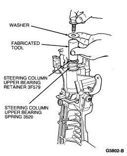
| 4 | 3C674 | Steering Column Upper Bearing Spring |
| 5 | 3N725 | Steering Column Lower Yoke |
| A | Tighten to 41-57 Nm (31-42 Lb-Ft) |
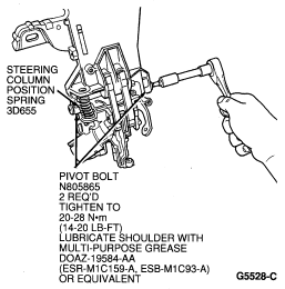
NOTE: Lube pivot bolts with Multi-Purpose Grease D0AZ-19584-AA or equivalent meeting Ford specification ESR M1C159-A and ESB M1C93-A before installing.