Section 05-02C: Differential, Traction-Lok Limited Slip—8.8 Inch Ring Gear | 1994 Mustang Workshop Manual |
DISASSEMBLY AND ASSEMBLY
Differential Case
Removal and Installation
Refer to Section 05-02B for Removal and Installation procedures. The
Traction-Lok differential case (4204)
is removed and installed in the same manner as a
conventional differential.
NOTE: It is not necessary to remove the differential bearings from the case
journals unless they are damaged. If the bearings remain on the differential case
during service, take care to keep them clean and free from foreign
material.
Disassembly
SPECIAL SERVICE TOOL(S) REQUIRED
| Description |
Tool Number |
| Gear Rotator-Traction-Lok |
T80P-4205-A |
- Remove and discard the 10 rear axle differential gear case bolts (4216)
securing the ring gear to the differential case
assembly.
- Remove the ring gear by tapping the gear with a soft-faced hammer or press
the gear from the differential case
.
- Remove the differential pinion shaft lock pin (4241)
and remove the differential pinion shaft (4211)
.
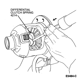
 WARNING: CARE MUST BE USED WHEN REMOVING THE DIFFERENTIAL CLUTCH SPRING (4214)
DUE TO SPRING TENSION.
WARNING: CARE MUST BE USED WHEN REMOVING THE DIFFERENTIAL CLUTCH SPRING (4214)
DUE TO SPRING TENSION.
- With a suitable drift, drive out the S-shaped differential clutch spring
.
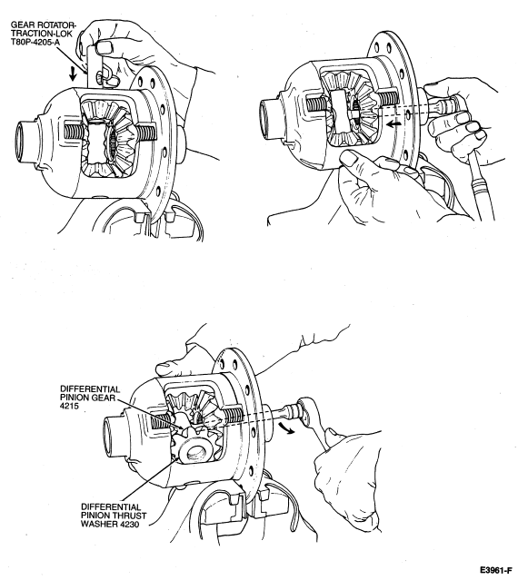
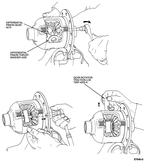
- Using Gear Rotator-Traction-Lok T80P-4205-A, rotate the differential pinion gears (4215)
until the gears and differential pinion thrust washers (4230)
can be removed.
- Remove the differential side gears (4236)
, differential clutch packs (4947)
and rear axle differential clutch shims (4A324)
from the RH and LH cavities and tag them
"RH" and "LH".
NOTE: Do not use cleaning solvents on friction plate surfaces. Wipe clean only.
- Clean and inspect all parts for wear or damage, replace as necessary.
Assembly
- Lubricate all parts with rear axle lubricant prior to assembly.
- Mount the differential case
in a soft-jaw vise and place the differential clutch packs
and differential side gears
in their proper cavities in the differential case
.
- Place the differential pinion gears
and differential pinion thrust washers
on the differential side gears
.
- Install Gear Rotator Traction-Lok T80P-4205-A in the differential case
.
- Rotate the differential pinion gears
until the bores in the gears are aligned
with the pinion shaft holes in the differential case
. Remove the tool from the differential case
.
NOTE: Inspect the differential clutch spring
for damage.
- With a soft-faced hammer, install the S-shaped differential clutch spring
in the differential case
. If necessary, complete the installation of S-shaped differential clutch spring
with a brass drift.
NOTE: Do not tighten the differential pinion shaft lock pin
at this point. The differential pinion shaft
and differential pinion shaft lock pin
will be removed to install the axle shafts. Once the differential side gears
and rear axle shaft retaining u-washers (4N237)
are installed, then the differential pinion shaft
and differential pinion shaft lock pin
may be installed and tightened to specification.
- Install the differential pinion shaft
and differential pinion shaft lock pin
.