 CAUTION: Handle the crankshaft
with care to avoid possible fracture or damage to the finished
surfaces.
CAUTION: Handle the crankshaft
with care to avoid possible fracture or damage to the finished
surfaces.
Section 03-01B: Engine, 5.0L HO and 5.0L Cobra | 1994 Mustang Workshop Manual |
Removal
CAUTION: Handle the crankshaft
with care to avoid possible fracture or damage to the finished
surfaces.
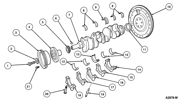
| Item | Part Number | Description |
|---|---|---|
| 1 | 388813 | Bolt 5/8-18 |
| 2 | 6378 | Damper Washer |
| 3 | 6312 | Engine Front Cover Spacer |
| 4 | 6316 | Crankshaft Damper |
| 5 | 6306 | Crankshaft Sprocket |
| 6 | 388907 | Crankshaft Key |
| 7 | 6303 | Crankshaft |
| 8 | 6333 | Crankshaft Main Upper Bearing |
| 9 | 6337 | Crankshaft Main Upper Thrust Bearing |
| 10 | 6375 | Flywheel |
| 11 | 6701 | Crankshaft Rear Oil Seal |
| 12 | 6333 | Crankshaft Main Lower Bearing |
| 13 | 6337 | Crankshaft Main Lower Thrust Bearing |
| 14 | � | Main Bearing Rear Cap (Part of 6010) |
| 15 | � | Main Bearing Rear Intermediate Cap (Part of 6010) |
| 16 | � | Main Bearing Center Cap (Part of 6010) |
| 17 | � | Main Bearing Front Intermediate Cap (Part of 6010) |
| 18 | � | Main Bearing Front Cap (Part of 6010) |
| 19 | 391546 | Main Bearing Cap Stud |
| 20 | 351547 | Main Bearing Cap Bolt (9 Req'd) |
| 21 | N804586-S6 | Bolt (4 Req'd) |
Installation
CAUTION: Be careful not to damage the bearing surfaces. Possible engine damage
may occur.
CAUTION: Ensure main bearing caps are installed in their original locations or
possible damage to engine may occur. Tighten the bearing cap bolts to 81-95 Nm
(60-70 lb-ft).