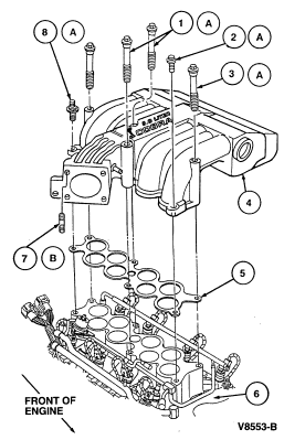
Mustang
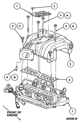
| Item | Part Number | Description |
|---|---|---|
| 1 | 9E434 | Cover Plate |
| 2 | 390652 | Screw (4 Req'd) |
| 3A | 391176 | Bolt (2 Req'd) |
| 4A | 56335 | Bolt (2 Req'd) |
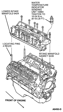
| 5 | 9424 | Upper Intake Manifold |
| 6 | 9H486 | Intake Manifold Upper Gasket |
| 7 | 9424 | Lower Intake Manifold |
| 8B | 390591 | Stud (4 Req'd) |
| 9A | 390358 | Bolt (2 Req'd) |
| A | Tighten to 16-24 Nm (12-18 Lb-Ft) | |
| B | Tighten to 2.7-5.4 Nm (2-4 Lb-Ft) |
 WARNING: RELIEVE FUEL LINE PRESSURE BEFORE DISASSEMBLING CONNECTIONS.
DISCONNECT AND CAP FUEL SUPPLY AND RETURN LINES. REFER TO SECTION 03-13 FOR
PROCEDURES.
WARNING: RELIEVE FUEL LINE PRESSURE BEFORE DISASSEMBLING CONNECTIONS.
DISCONNECT AND CAP FUEL SUPPLY AND RETURN LINES. REFER TO SECTION 03-13 FOR
PROCEDURES.