Section 03-01A: Engine, 3.8L | 1994 Mustang Workshop Manual |
Removal
Leaving hoses connected, place pump/bracket assembly aside in a position to prevent fluid from leaking out.
Installation
NOTE: Lightly oil all bolts and stud bolt threads before installation except those specifying special sealant.
 CAUTION: Always use new cylinder head bolts to ensure a leak-tight assembly.
Torque retention with used bolts can vary, which may result in coolant or
compression leakage at the cylinder head mating surface area.
CAUTION: Always use new cylinder head bolts to ensure a leak-tight assembly.
Torque retention with used bolts can vary, which may result in coolant or
compression leakage at the cylinder head mating surface area.
NOTE: When cylinder head retaining bolts have been tightened using the following procedure, it is not necessary to retighten bolts after extended engine operation. However, bolts can be checked for tightness if desired.
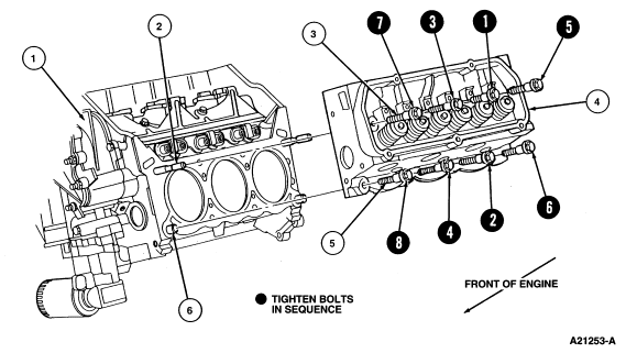
CAUTION: Do not loosen all of the bolts at the same time; only work on one bolt
at a time.
Long bolts:
Short Bolts:
| Item | Part Number | Description |
|---|---|---|
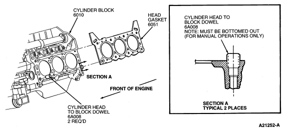
| 1 | 6010 | Cylinder Block |
| 2 | � | Locating Pin (2 Req'd) |
| 3 | N802515-S | Cylinder Head Bolt (4 Req'd Each Side) |
| 4 | 6049 | Cylinder Head |
| 5 | N802516-S | Cylinder Head Bolt (4 Req'd Each Side) |
| 6 | 6A008 | Cylinder Head to Block Dowel |
NOTE: If original valve train components are being installed, a valve clearance check is not required. If a component has been replaced, perform a valve clearance check. Refer to Section 03-00.
Install push rods in their original position.
CAUTION: This engine has aluminum cylinder heads and requires a special
corrosion inhibited coolant formulation to avoid cooling system damage. Refer
to Section 03-03 for the coolant specifications.