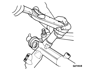
 CAUTION: Do not allow rack to reach full travel when loosening or tightening
the locknut as damage to rack teeth may result.
CAUTION: Do not allow rack to reach full travel when loosening or tightening
the locknut as damage to rack teeth may result.
Section 11-02: Steering System, Power | 1994 Mustang Workshop Manual |
| Description | Tool Number |
|---|---|
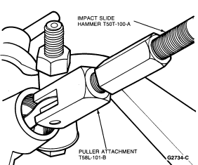
| Impact Slide Hammer | T50T-100-A |
| Bench Mounted Holding Fixture | T57L-500-B |
| Puller Attachment | T58L-101-B |
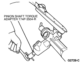
| Pinion Shaft Torque Adapter | T74P-3504-R |
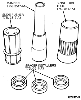
| Mandrel | T75L-3517-A1 |
| Pusher | T75L-3518-A2 |
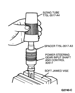
| Spacer | T75L-3517-A3 |
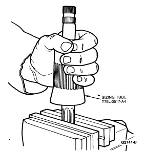
| Sizing Tube | T75L-3517-A4 |
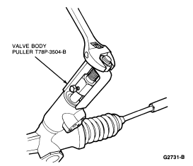
| Valve Body Puller | T78P-3504-B |
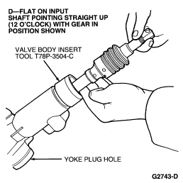
| Valve Body Insert Tool | T78D-3504-C |
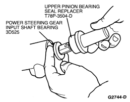
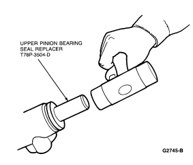
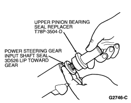
| Upper Pinion Bearing Seal Replacer | T78P-3504-D |
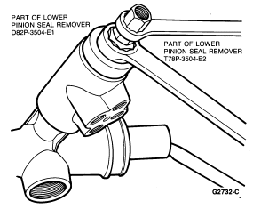
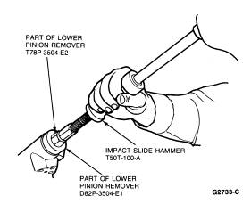
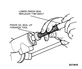
| Lower Pinion Seal Remover | T78P-3504-E2 |
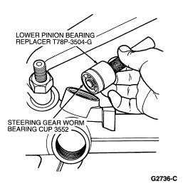
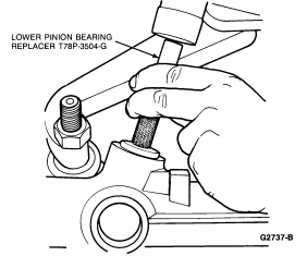
| Lower Pinion Bearing Replacer | T78P-3504-G |
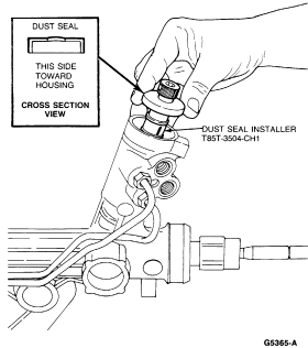
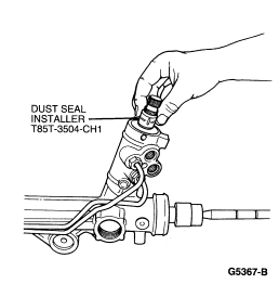
| Dust Seal Installer | T85T-3504-CH1 |
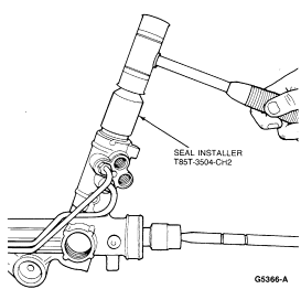
| Seal Installer | T85T-3504-CH2 |
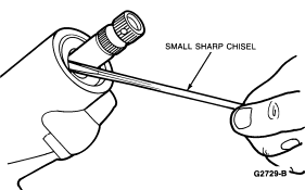
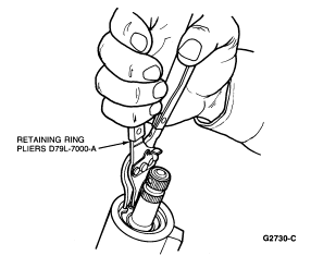
Disassembly
CAUTION: Do not allow rack to reach full travel when loosening or tightening
the locknut as damage to rack teeth may result.
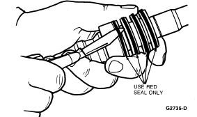
CAUTION: Use care not to damage any of the valve housing surfaces.
CAUTION: Use care not to scratch the valve sleeve as it may leak internally.
Assembly
| Item | Part Number | Description |
|---|---|---|
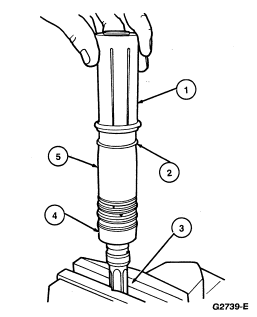
| 1 | T75L-3517-A2 | Pusher |
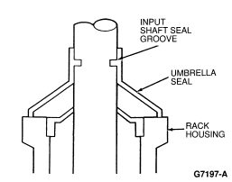
| 2 | 3D527 | Power Steering Gear Input Shaft Dust Seal |
| 3 | � | Soft-Jawed Vise |
| 4 | 3D517 | Power Steering Gear Input Shaft and Control |
| 5 | T75-3517-A1 | Mandrel |
NOTE: If only the valve was serviced and the rack was not moved while the valve was out, Step 9 may be omitted.
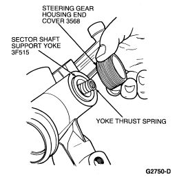
NOTE: Yoke must seat against the rack with finger pressure. If yoke hangs up, check for burrs in yoke housing.