Section 05-00: Axle and Driveshaft—Service | 1994 Mustang Workshop Manual |
CLEANING AND INSPECTION
Inspection Before Carrier Disassembly
Integral Carrier
SPECIAL SERVICE TOOL(S) REQUIRED
| Description |
Tool Number |
| Pinion Depth Gauge |
T79P-4020-A |
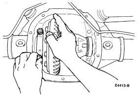
Inspect the parking brake lever boot retainer (2405)
assembly and drive pinion before they are removed from the rear axle housing (4010)
. These inspections can help find the cause of the trouble and
determine the correction needed.
- Wipe the lubricant from the internal working parts and visually inspect the
parts for wear and/or damage.
- Rotate the gears to see if there is any roughness which would indicate worn
or damaged bearings or gears.
- Check the ring gear teeth for signs of scoring, abnormal wear, nicks or
chips.
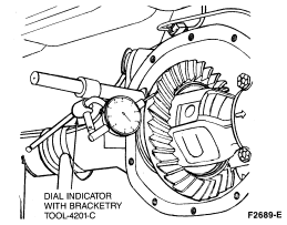
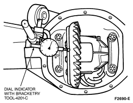
- Set up a dial indicator, and check ring gear backlash and ring gear
backface runout.
- Proper differential ring gear and pinion (4209)
assembly must be checked using the Pinion Depth Gauge
T79P-4020-A which shows correct drive pinion bearing adjustment shim (4663)
required to ensure acceptable running condition.
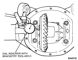
Ring and Pinion Backlash Check
This indicates runout conditions that will not show up in other tests.
Remove the axle housing cover (4033)
. Refer to Section 05-02A (7.5-inch Ring Gear) or Section 05-02B
(8.8-inch Ring Gear). Measure ring gear backlash on 30 consecutive ring gear
teeth using Dial Indicator with Bracketry TOOL-4201-C or equivalent. Note the
variation between the high and low readings. If over 0.10mm (0.004 inch),
replace the differential ring gear and pinion
. Install the axle housing cover
.
Ring Gear Runout Check
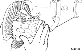
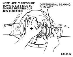
- With the pinion removed, place differential case/gear subassembly with differential bearings (4221)
and differential bearing cups (4222)
in rear axle housing.
- Install a 6.75 mm (0.265-inch) differential bearing shim (4067)
on the LH side of subassembly.
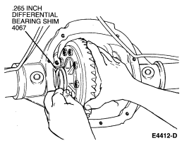
- Install the LH bearing cap finger-tight.
- Install progressively larger differential bearing shims
on the RH side until the largest differential bearing shim
selected can be assembled with a slight drag feel.
- Install the RH side bearing cap. Install bearing cap bolts. Tighten both RH
and LH bolts to 95-115 Nm (70-85 lb-ft).
- Rotate the assembly to ensure free rotation.
- Check and note ring gear runout.
- If the runout is within specification, refer to Section 05-02A (7.5-inch
Ring Gear) or Section 05-02B (8.8-inch Ring Gear).