Reference Definitions
Section 04-00: SuspensionŚService | 1994 Mustang Workshop Manual |
Do not attempt to check and adjust front-wheel alignment without first making a preliminary inspection of the front end parts.
Check all the factors of front-wheel alignment, except the turning angle, before making any adjustments. Check the turning angle only after camber and toe have been adjusted to specification. Check the front-wheel alignment under the following curb load conditions:
Refer to Specifications for front-wheel alignment specifications.
Equipment Installation
Equipment used for front-wheel alignment inspection must be accurate. All wheel alignment readings must be performed on an alignment rack level to within 1.59mm (1/16 inch) side-to-side and front-to-rear. The instrumentation used must have a means of compensating for wheel runout.
Install the wheel alignment equipment on the vehicle and follow the installation and inspection instructions provided by the manufacturer.
After front-wheel alignment factors have been checked, make the necessary adjustments. Do not attempt to adjust front-wheel alignment by bending the suspension or steering parts.
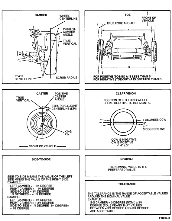
Camber
Camber is the amount that the centerline of the wheel is tilted inward or outward from the true vertical. If the top of the wheel is tilted outward, away from the vehicle, the camber is positive. If the top of the wheel is tilted inward, toward the vehicle, the camber is negative. For correct camber angle, refer to Specifications.
The maximum camber difference (side-to-side) is shown in Specifications.
Camber is adjusted by removing the pop-rivet in the front suspension camber adjusting plate (3B391) . Loosen the two nuts and one bolt which hold the strut mount to the body apron. Camber is adjusted by moving the top of the shock strut to the desired position. It is not necessary to replace the pop-rivet.
Caster
NOTE: The caster is preset at the factory and cannot be changed. Toe and camber are adjustable.
The caster is the forward or rearward tilt of the top of the front wheel spindle (3105) . If the top of the front wheel spindle tilts to the rear, caster is positive. If the top of the spindle tilts to the front, caster is negative. For correct caster angle, refer to Specifications.
The maximum caster difference (side-to-side) is shown in Specifications.
Toe
Toe should only be checked and adjusted after the caster and camber have been adjusted to specification.
Toe-in and toe-out is the difference in the distance between the extreme front and extreme rear of the tires. Toe-in occurs when the dimension taken at the front of the tires is less than that taken at the rear of the tiresŚpositive toe. Toe-out occurs when the dimension taken at the front of the tires is greater than that taken at the rear of the tiresŚnegative toe.
For correct toe setting, refer to Specifications.
Start the engine and move the steering wheel (3600) back and forth several times until it is in the straight-ahead position, so that the power steering control valve, if so equipped, will be in the center (neutral) position. Lock the steering wheel in place at -1.4 degrees (counter clockwise) using a steering wheel holder.
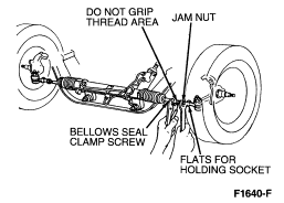
NOTE: Whenever the jam nuts are loosened for toe adjustment, the nut and front wheel spindle connecting rod or end threads must be cleaned and lubricated and the jam nut tightened to 48-68 Nm (35-50 lb-ft).
Adjust the LH and RH front wheel spindle connecting rod or end lengths,
until each wheel
has one-half of the desired total toe specification.
Reference Definitions
Tire and Wheel Runout
Excessive radial and lateral runout of a wheel and tire assembly can cause roughness, vibration, wheel tramp, tire wear, and steering wheel nibble (tremor).
To avoid false readings caused by temporary flat spots in the tires, check runout only after the vehicle has been driven. Visually inspect the tire carcass for abnormal bulges, distortions, etc.
The extent of runout should be measured with Radial Run-Out Gauge 007-00014 or equivalent. All measurements should be made on the vehicle with the tires inflated to recommended load inflation pressures and with the wheel bearing adjusted to specification.
For service and adjustment, refer to Section 00-04.