Section 03-06: Starting System | 1994 Mustang Workshop Manual |
DIAGNOSIS AND TESTING
Component Tests
Starter
Load Test
Conduct this test if the starter motor (11002)
cranks slowly and it is desired to compare current to
specifications.
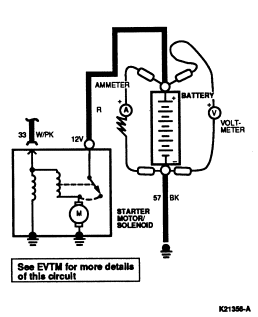
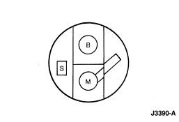
- Connect Rotunda Starting and Charging Tester 078-00005 or equivalent. Make
sure that current is not flowing through ammeter and heavy-duty carbon pile
rheostat portion of circuit (rheostat at maximum counterclockwise position).
NOTE: Make sure ignition switch (11572)
is in the OFF position and S-terminal connector has
been removed so engine does not start.
- Place transmission in NEUTRAL or PARK. Crank engine with ignition switch
OFF, and determine exact reading on voltmeter. This
test is accomplished by disconnecting push-on connector S at starter solenoid (11390)
and by connecting a remote control starter switch from
positive battery terminal to S-terminal of starter solenoid
.
- Stop cranking engine, and reduce resistance of carbon pile until voltmeter
indicates same reading as that obtained while starter motor
cranked the engine. The ammeter will indicate starter
current draw under load. Check this with value listed in Starter Specifications.
Voltage Drop Tests
If the starter motor
cranks slowly and the battery (10653)
is satisfactory, there may be a malfunction of the starter motor
or in the cranking circuit wiring. To determine if the
problem is in the wiring, a voltage drop test must be performed.
These tests are performed to determine if there is excessive resistance
in the starter motor circuit. Always make the volt-ohmmeter connections at the
component terminal rather than at the cable wiring end connector. Making a
connection at the wiring end connector could result in false readings because
the meter will not pick up a high resistance between the wiring connector and
the component.
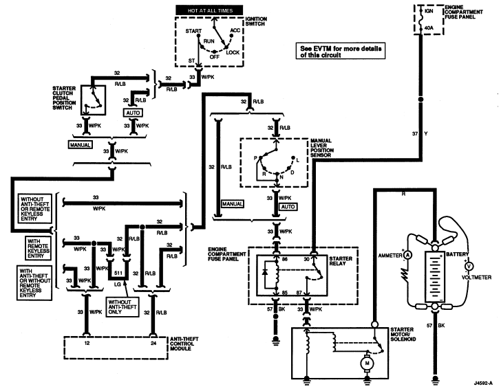
Motor Feed Circuit
- Prevent the engine from starting by disconnecting the ignition coil (12029)
.
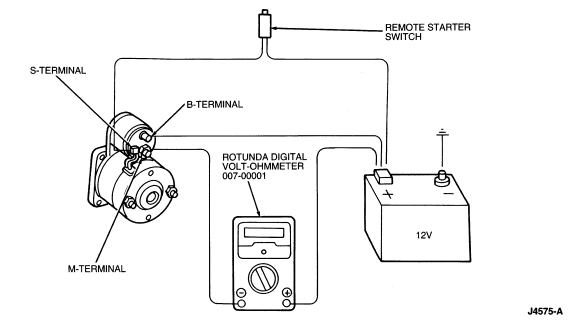
- Connect a remote starter switch between the starter solenoid S-terminal and
the battery positive (+) terminal.
- Connect Rotunda Digital Volt-Ohmmeter 007-00001 or equivalent positive lead
to the battery positive (+) post. Connect Rotunda Digital Volt-Ohmmeter
007-00001 or equivalent negative lead to the solenoid M-terminal.
- Engage the remote starter switch. Read and record the voltage. The voltage
reading should be 0.5 volt or less.
- If the voltage reading is higher than this, indicating excessive
resistance, move the volt-ohmmeter negative lead to the starter solenoid
B-terminal and repeat the test. If the voltage reading at the B-terminal is
lower than 0.5 volt, the concern is either in the connections at the solenoid
or in the solenoid contacts.
- Remove the cables from solenoid B-, S-, and M-terminals. Clean the cables
and connections and reinstall the cables to the proper terminals. Repeat Steps
1 through 5 above. If the voltage drop reading is still higher than 0.5 volts
when checked at the M-terminal or lower when checked at the B-terminal, the
concern is in the solenoid contacts. Remove and replace the starter motor
or starter solenoid
, if available.
- If the voltage reading taken at the solenoid B-terminal is still higher
than 0.5 volt after cleaning the cables and connections at the solenoid, the
concern is either in the positive (+) battery cable connection, or in the
positive battery cable itself.
- By moving the volt-ohmmeter negative lead toward the battery
and checking each mechanical connection point, the
excessive voltage drop can be located. When the high reading disappears, the
last mechanical point that was checked is the concern.
Motor Ground Circuit
A slow cranking condition can be caused by resistance in the ground or
return portion of the cranking circuit. Check the voltage drop in the ground
circuit as follows:
- Prevent the engine from starting by disconnecting the ignition coil
.
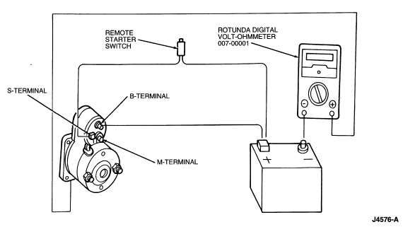
- Connect a remote starter switch between the starter solenoid S-terminal and
the battery positive (+) terminal.
- Connect a Rotunda Digital Volt-Ohmmeter 007-00001 or equivalent positive
lead to the starter motor housing (connection must be clean and free of rust or
grease). Connect Rotunda Digital Volt-Ohmmeter 007-00001 or equivalent negative
lead to the negative (-) battery terminal.
- Engage the remote starter switch and crank the engine. Read and record the
volt-ohmmeter reading. The reading should be 0.2 volt or less.
- If the voltage drop is more than 0.2 volt, clean the negative cable
connections at the battery and body connections, and retest. If the voltage
drop is still too high, perform the following test:
Individual Cable
The resistance of any cable can be checked in the same manner by using
Rotunda Digital Volt-Ohmmeter 007-00001 or equivalent.
- Determine which way the current is flowing in the cable. Connect Rotunda
Digital Volt-Ohmmeter 007-00001 or equivalent positive lead to the end of the
cable nearest battery positive.
- Connect Rotunda Digital Volt-Ohmmeter 007-00001 or equivalent negative lead
to the terminal at the other end of the cable.
- Crank the engine and observe Rotunda Digital Volt-Ohmmeter 007-00001 or
equivalent. The voltage reading should be 0.2 volt or lower. If the voltage
drop is too high, clean the terminal ends. Retest, and if still high, replace
the cable.
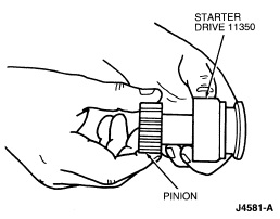
Motor Pinion Test
- Turn the pinion by hand and hold the overrunning clutch. Replace the starter drive (11350)
if the pinion turns in both directions or does not turn.
No-Load Test
The starter no-load test will uncover such conditions as open or shorted
windings, or rubbing starter motor armature (11005)
. The starter motor
can be tested, at no-load, on the test bench only.
 CAUTION: Make sure that the starter motor
is securely mounted in bench vise while energizing, as starter motor
will move or jump.
CAUTION: Make sure that the starter motor
is securely mounted in bench vise while energizing, as starter motor
will move or jump.
- Make test connections with Rotunda Starting and Charging Tester 078-00005
or equivalent cables connected to starter motor
, large enough to carry high current (the same as in the
vehicle). The starter motor
will run at no-load. Be sure that no current is flowing
through ammeter (rheostat at maximum counterclockwise position). Determine
exact reading on voltmeter.
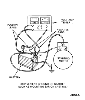
- Disconnect starter motor
from battery
. Then, reduce resistance of rheostat until voltmeter
indicates same reading as that obtained while starter motor
was running. The ammeter will indicate starter motor
no-load current draw. Refer to Starter Specifications at the end of this
Section for a comparative value.
- If current exceeds specification, check for rubbing starter motor armature
, bent output shaft (11355)
, binding bushings, or shorts in starter motor armature
, or brush holder (11061)
.
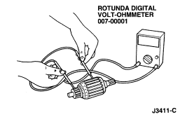
Armature
Open Circuit Test
An open circuit starter motor armature
may sometimes be detected by examining the commutator
for evidence of burning. A burn spot on the commutator is caused by an arc
formed every time the commutator segment, connected to the open circuit
winding, passes under a brush.
Grounded Circuit Test
This test will determine if the winding insulation has been damaged,
permitting a conductor to touch the frame or starter motor armature core. To
determine if the starter motor armature windings are grounded, check with a
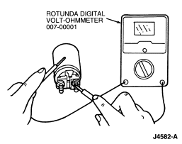
Rotunda Digital Volt-Ohmmeter 007-00001 or equivalent. Infinite resistance
indicates a normal condition.
Starter Solenoid
Ensure that the starter solenoid
is isolated electrically from the starter motor
. Using a Rotunda Digital Volt-Ohmmeter 007-00001 or
equivalent, check for continuity between S-terminal and M-terminal, and between
S-terminal and ground ( starter frame and magnet (11075)). If there is no continuity, the
following conditions
may exist:
- Open wire; replace starter solenoid
.
- Ice, dirt or other foreign material preventing contact; service as
necessary.
Solenoid S-Terminal Circuit Resistance
Using Rotunda Digital Volt-Ohmmeter 007-00001 or equivalent, check the
resistance of the entire S-terminal circuit, including all the switches, wires,
and connections. Resistance should be less than 0.08 ohm.
Solenoid M-Terminal
- Using Rotunda Digital Volt-Ohmmeter 007-00001 or equivalent, check for
continuity between the solenoid M-terminal and the solenoid housing.
- If there is no continuity, replace the starter solenoid
.