Section 12-03A: Air Conditioning System | 1993 Mustang Workshop Manual |
| Description | Specifications |
|---|---|
| System Protection | |
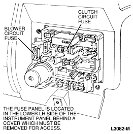
| Blower Circuit | 30 Amp Fuse (Lt. Green) in Panel |
| Clutch Circuit | 20 Amp Fuse (Natural) in Panel |
| Blower Resistor Circuit | Thermal Limiter (Integral Resistor) |
| Blower Motor Current Draw | |
| Low | 3.5-5 Amps/3.5-4.5 Volts |
| Medium Low | 6-8 Amps/5.5-7 Volts |
| Medium High | 10-14 Amps/7.5-10.5 Volts |
| High | 16-22 Amps/11-14 Volts |
| Description | Specifications |
|---|---|
| System Protection | |
| Pressure Switch | Close Max. 47 psi
Open Max. 23 psi |
| Compressor | Clutch Cycling Pressure Switch2 | Fixed Orifice Tube | Refrigerant Capacity | ||
|---|---|---|---|---|---|
| 6P148 | 10P15C | (Oz.) | (Kg.) | ||
| X1 | X | X | X | 34±1 | 0.964±0.028 |
| Description | Nm | Lb-Ft | Lb-In |
|---|---|---|---|
| Compressor Clutch Retaining Bolt | 28-40 | 21-29 | |
| Compressor-to-Bracket(s) Attaching Bolts | |||
| 2.3L | 37-56 | 28-41 | |
| 5.0L | 41-61 | 31-44 | |
| Compressor Bracket-to-Engine | |||
| 2.3L | 56-85 | 42-62 | |
| 5.0L | 41-61 | 31-44 | |
| Compressor Support Brace-to-Engine | |||
| 2.3L | 56-85 | 42-62 | |
| 5.0L | 41-61 | 31-44 | |
| Idler Retaining Bolts
4 and 8 Cylinder |
41-61 | 31-44 | |
| Refrigerant Hose Fittings | |||
| Compressor-to-Suction Hose | 28-36 | 21-26 | |
| Compressor-to-Discharge Hose | 20-27 | 15-19 | |
| Pressure Switch to Accumulator Nipple | Hand | Tighten | |
| Liquid Line-to-Evaporator Core | 15-18 | 12-13 | |
| Accumulator-to-Evaporator Core | 28-36 | 21-26 | |
| Liquid Line at Orifice Tube | 28-36 | 21-26 | |
| Suction Line at Accumulator | 28-36 | 21-26 | |
| Support Brace to Compressor
(2.3L) |
37-56 | 27-42 | |
| Condenser Bracket to Radiator | |||
| Support (Screw) | 8-14 | 6-10 | |
| Orifice Tube Compression Nut | 88-94 | 65-65 | |
| Condenser to Bracket (Nut) | 16-24 | 12-17 |