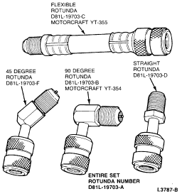
Service Access High Pressure Adapter
Section 12-03A: Air Conditioning System | 1993 Mustang Workshop Manual |
The manual A/C-heater refrigerant system uses an A/C compressor, a condenser, an evaporator core, a fixed orifice tube in the liquid line near the condenser, a pressure switch, Schrader-type service access gauge port valves and the necessary refrigerant lines for the system.
Service Access Gauge Port Valves
Two Schrader-type service access gauge port valves are used with the
refrigerant system. Both valves are located on the refrigerant lines. The high
pressure service access gauge port valve requires an adapter to attach a
refrigerant service hose to it. The various adapters available are shown in the
following illustration.
Service Access High Pressure Adapter

Always replace the caps on the service access gauge port valves after servicing the refrigerant system.
Evaporator Core
The evaporator core is a multi-pass plate/fin-type core mounted in a vertical position. Vaporized refrigerant enters the core at the lower corner and flows through the first three plate/fin sections to the other end of the core. The refrigerant flow then reverses and flows through the next three plate/fin sections to the opposite end of the core where the flow again reverses and flows through the remaining four plate/fin sections to the inserted suction tube. This S-pass flow pattern accelerates the flow of refrigerant through the evaporator core which does not have a liquid bleed line. The multi-pass core can be identified by a paint spot on the suction tube, a blue shipping cap and folded down locator tabs.
Fixed Orifice Tube
The fixed orifice tube assembly is the device which provides a
restriction between the high and low pressure liquid refrigerant and meters the
flow of liquid refrigerant into the evaporator core. Evaporator temperature is
controlled by sensing the pressure within the evaporator with a pressure
operated electric switch. The pressure switch controls compressor operation as
necessary to maintain the evaporator pressure within specified limits.
Fixed Orifice Tube
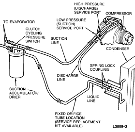
The fixed orifice tube is located in the liquid line near the condenser and has filter screens located on the inlet and outlet ends of the tube body. The filter screens act as a strainer for the liquid refrigerant flowing through the fixed orifice opening. O-rings, on the tube body, prevent the high pressure liquid refrigerant from bypassing the orifice. Adjustment or services cannot be made to the fixed orifice tube assembly and it must be replaced as a unit.
Suction Accumulator/Drier
The suction accumulator/drier is mounted to the engine side of the dash
panel on the right side of the vehicle. The inlet tube of the accumulator/drier
attaches directly to the evaporator core outlet tube. Refrigerant enters the
accumulator/drier canister through the inlet tube and the heavier oil-laden
refrigerant falls to the bottom of the canister. A small diameter oil bleed
hole is located in the side of the outlet tube near the bottom of the canister.
This bleed hole is covered with a filter and allows a small amount of the
heavier liquid refrigerant and oil mixture to re-enter the suction line at a
controlled rate. When the heavier liquid refrigerant and oil mixture enters the
compressor suction line, it has a second opportunity to vaporize and circulate
through the compressor without causing damage to the compressor due to
refrigerant slugging.
Suction Accumulator/Drier
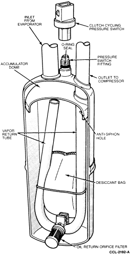
A desiccant bag is mounted inside the suction accumulator/drier canister to absorb any moisture which may be in the refrigerant system.
A fitting located on the top of the canister is used to attach the clutch cycling pressure switch. A long travel Schrader-type valve stem core is installed in the fitting opening to prevent refrigerant loss when the clutch cycling pressure switch is removed.
Clutch Cycling Pressure Switch
The clutch cycling pressure switch is mounted on a Schrader valve-type fitting on the top of the suction accumulator/drier assembly. A valve depressor, located inside the threaded end of the pressure switch, presses in on the Schrader valve stem as the switch is mounted and allows the suction pressure inside the accumulator/drier canister to control switch operation. The electrical switch contacts are normally open when the suction pressure is approximately 152-193 kPa (22-28 psi), they will close when the suction pressure rises to approximately 276-324 kPa (40-47 psi) or above. Lower ambient temperatures (below approximately 10°C or 50° F) during cold weather will also open the clutch cycling pressure switch contacts due to the pressure/temperature relationship of the refrigerant in the system. The electrical switch contacts control the electrical circuit to the compressor magnetic clutch coil. When the switch contacts are closed, the clutch coil is energized and the A/C clutch is engaged to drive the compressor. When the switch contacts are open, the compressor magnet clutch coil is de-energized, the A/C clutch is disengaged and the compressor does not operate. The clutch cycling pressure switch, when functioning properly, will control the evaporator core pressure at a point where the plate/fin surface temperature will be maintained slightly above freezing which prevents evaporator icing and the blockage of airflow.
A/C Time Delay and WOT Cutout Switch
2.3L or 5.0L Engine
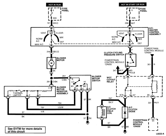
5.0L engines are equipped with a wide-open throttle (WOT) cutout switch to prevent compressor operation during wide-open throttle operation. The WOT cutout switch is connected in series with the A/C time delay relay and de-energizes the relay to stop compressor operation when the switch opens. The compressor will not operate as long as the WOT cutout switch is open. When the WOT cutout switch closes, the time delay relay continues to prevent compressor operation for five seconds before allowing the compressor to return to normal operation. The 5.0L WOT relay is located on the RH fender apron forward of the shock tower.
The A/C time delay relay is located under the instrument panel to the
left of the steering column and is an integral part of the cooling fan
controller used on all 2.3L engines.
A/C Time Delay Relay and WOT Cut-Out Switch Electrical Schematic—2.3L
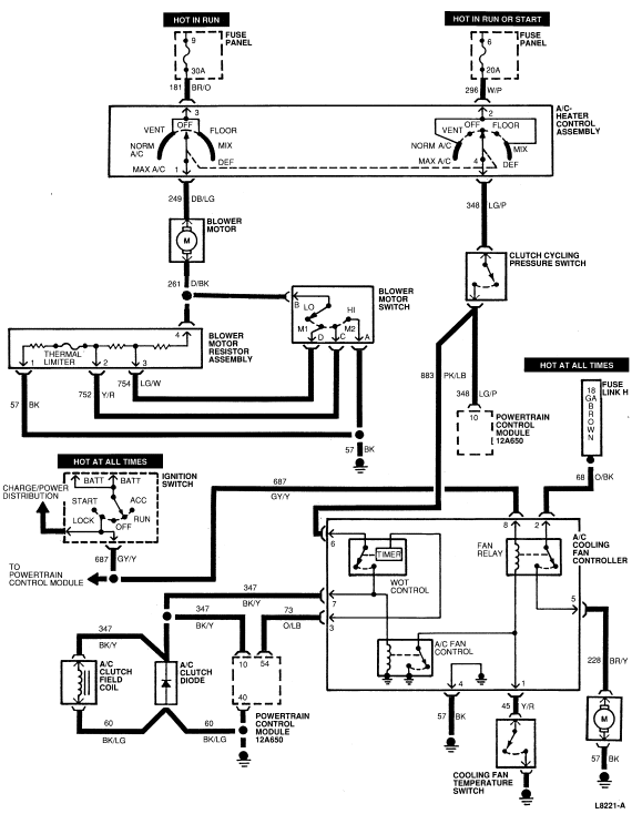
A/C Time Delay Relay and WOT Cut-Out Switch Electrical Schematic—5.0L
Condenser Assembly
The A/C condenser is an aluminum fin and tube design heat exchanger located in front of the vehicle radiator. It cools compressed refrigerant gas by allowing air to pass over the fins and tubes to extract the heat and condenses the gas to liquid refrigerant as it is cooled.
The condenser inlet and outlet connections are the male part of a spring lock coupling and require a special service tool to disconnect the refrigerant lines from the condenser.
A/C Compressor and Clutch
6P148 Compressor
The 6P148 compressor is a swashplate design, six-cylinder unit driven by a belt from the engine crankshaft. The 6P148 is built by Nipondenso with a displacement of 148cc (9.0 cubic inches). Lubrication is provided by a charge of 500 viscosity refrigerant oil in the refrigerant system.
The suction and discharge manifolds are attached to the top of the compressor with two screws and the pressure relief valve is threaded into the discharge manifold. The 6P148 uses cast aluminum manifolds.
The clutch consists of three basic components: the pulley, hub and the field coil. The pulley and field coil are attached to the front lead of the compressor with tapered snap rings. The hub is keyed to the compressor shaft and is retained to the shaft with a nut and lock washer.
Refer to Section 12-03C for compressor and clutch service procedures.
10P15C Compressor
The 10P15C compressor is a 10-cylinder axial design compressor with mounting brackets for tangential mounting. The compressor shaft is driven by a belt from the engine accessory drive. Five double acting pistons, positioned axially around the compressor shaft, are actuated by a swashplate that is pressed on the compressor shaft. The swashplate uses the rotating action of the shaft to provide a reciprocating driving force to each of the five pistons. This driving force is applied, through balls and shoes, to the mid-point of each of the five double ended pistons.
Reed-type suction and discharge valve plates are located between the cylinder assembly and the head at each end of the compressor. The heads are connected with each other by gas-tight passageways which direct refrigerant gas to a common output.
A magnetic clutch is used to drive the compressor shaft. When voltage is applied to the clutch field coil, the clutch plate and hub assembly, (which is solidly coupled to the compressor shaft) is drawn by magnetic force toward the pulley which rotates freely on the compressor front head casting. The magnetic force locks the clutch plate and hub assembly and the pulley together as one unit. The compressor shaft then turns with the pulley. When voltage is removed from the clutch field coil, a rubber bushing in the clutch plate and hub assembly moves the clutch plate away from the pulley and the compressor shaft ceases to rotate.
Refer to Section 12-03B for illustrations and service procedures which apply to the 10P15C compressor and clutch.
Pressure Relief Valve
A pressure relief valve is installed on the compressor to relieve excessive high-pressure buildup (450 psi and above) and prevent damage to the compressor and other A/C components. The pressure relief valve is located on the side of the 6P148 and 10P15C compressor discharge (high pressure) manifold.
Spring Lock Coupling
The spring lock coupling, shown in in disconnected state, is a
refrigerant line coupling held together by a garter spring inside a circular
cage. When the coupling is connected, the flared end of the female fitting
slips behind the garter spring inside the cage of the male fitting. The garter
spring and cage then prevent the flared end of the female fitting from pulling
out of the cage.
Spring Lock Coupling
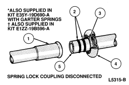
| Item | Part Number | Description |
|---|---|---|
| 1 | Female Fitting | |
| 2 | 391302-S100 391303-S100 391304-S100 391305-S100 |
3/8 inch O-Ring 1/2 inch O-Ring** 5/8 inch O-Ring** 3/4 inch O-Ring* |
| 3 | Garter Spring | |
| 4 | Cage | |
| 5 | Male Fitting |
*Also supplied in kit E35Y-19D690-D with Garter Springs.
**Also supplied in kit E35Y-19D690-D with Garter Springs and in kit E177-19B596-A.
Two O-rings are used to seal between the two halves of the coupling. These O-rings are made of special green material and must be replaced with an O-ring made of the same green material. The O-rings normally used in refrigerant system connections are not the same material and should not be used with the spring lock coupling. Use only the O-rings listed in the Ford Master Parts catalog for the spring lock coupling.
A plastic indicator ring is used on spring lock couplings to indicate, during vehicle assembly, that the coupling is connected. Once the coupling is connected, the indicator ring is no longer necessary but will remain captive by the coupling near the cage opening.
The indicator ring may also be used during service operations to indicate connection of the coupling. After the coupling has been cleaned, new green O-rings should be lubricated with clean refrigerant and installed. Insert the tabs of the indicator ring into the cage opening. Then, connect the coupling together by pushing with a slight twisting motion. When the coupling is connected, the indicator ring will snap out of the cage opening but will remain captured on the coupling by the refrigerant line.
Cooling Fan Controller
A cooling fan controller is used on all vehicles equipped with electro-drive cooling fan. For an illustration and further details regarding the cooling fan controller circuit, refer to the Electrical and Vacuum Troubleshooting Manual. The cooling fan controller is used to cycle the engine cooling fan on whenever the A/C compressor is operating. The controller also allows for engine cooling fan operation whenever the engine coolant temperature reaches 105°C (221°F).
The cooling fan controller is located under the instrument panel to the left of the steering column. Refer to Section 03-03 for diagnosis.