Section 01-20B: Restraints, Passive—Supplemental Air Bag System | 1993 Mustang Workshop Manual |
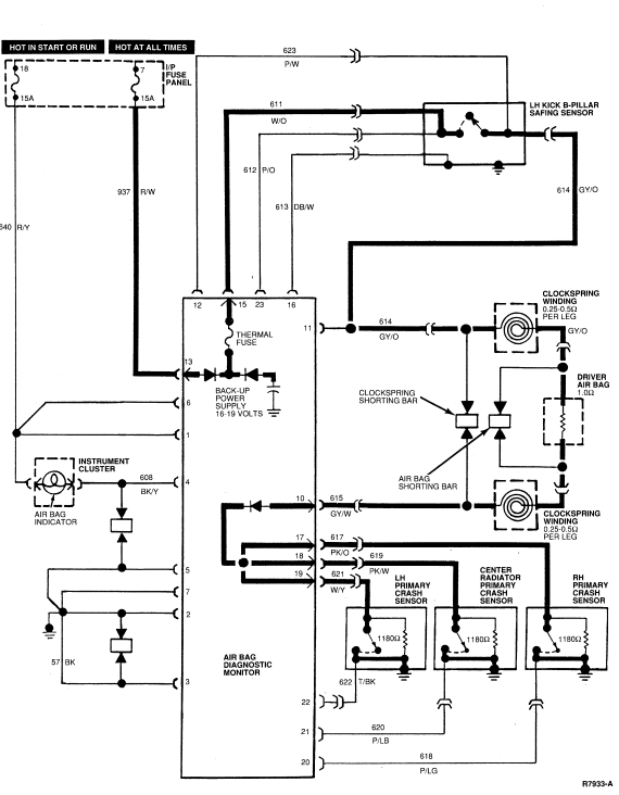
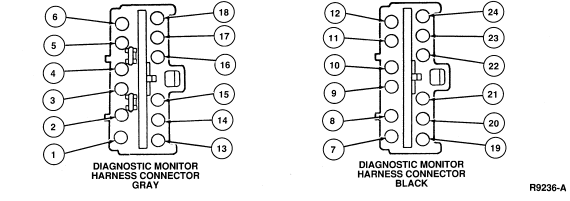
| PIN NO. | CIRCUIT/COLOR | DESCRIPTION |
|---|---|---|
| 1 | 640 (R/Y) | Power Input |
| 2 | 57 (BK) | Ground |
| 3 | 57 (BK) | Ground |
| 4 | 608 (BK/Y) | Air Bag Indicator Control |
| 5 | 57 (BK) | Ground |
| 6 | 640 (R/Y) | Power Input |
| 7 | 57 (BK) | Ground |
| 8 | — | NOT USED |
| 9 | — | NOT USED |
| 10 | 615 (GY/W) | Steering Column Air Bag Return |
| 11 | 614 (GY/O) | Steering Column Air Bag Feed Monitor |
| 12 | 623 (P/W) | Safing Sensor Output Monitor |
| 13 | 937 (R/W) | Battery Input |
| 14 | — | NOT USED |
| 15 | 611 (W/O) | Safing Sensor Feed |
| 16 | 613 (DB/W) | Safing Sensor Ground Monitor |
| 17 | 617 (PK/O) | Right Forward Primary Sensor Feed |
| 18 | 619 (PK/W) | Center Forward Primary Sensor Feed |
| 19 | 621 (W/Y) | Left Forward Primary Sensor Feed |
| 20 | 618 (P/LG) | Right Forward Primary Sensor Ground Monitor |
| 21 | 620 (P/LB) | Center Forward Primary Sensor Ground Monitor |
| 22 | 622 (T/BK) | Left Forward Primary Sensor Ground Monitor |
| 23 | 612 (P/O) | Safing Sensor Feed Monitor |
| 24 | — | Not Used |
| Vehicle Charging System Voltage | Pin No. 1 | Pin No. 2 | Pin No. 3 | Pin No. 4 | Pin No. 5 | Pin No. 6 | Pin No. 7 | Pin No. 8 |
|---|---|---|---|---|---|---|---|---|
| 9.0 | 9.0 | 0.0 | 0.0 | 9.0 | 0.0 | 9.0 | * | 1.9 |
| 9.5 | 9.5 | 0.0 | 0.0 | 9.5 | 0.0 | 9.5 | * | 2.0 |
| 10.0 | 10.0 | 0.0 | 0.0 | 10.0 | 0.0 | 10.0 | * | 2.1 |
| 10.5 | 10.5 | 0.0 | 0.0 | 10.5 | 0.0 | 10.5 | * | 2.2 |
| 11.0 | 11.0 | 0.0 | 0.0 | 11.0 | 0.0 | 11.0 | * | 2.3 |
| 11.5 | 11.5 | 0.0 | 0.0 | 11.5 | 0.0 | 11.5 | * | 2.4 |
| 12.0 | 12.0 | 0.0 | 0.0 | 12.0 | 0.0 | 12.0 | * | 2.5 |
| 12.5 | 12.5 | 0.0 | 0.0 | 12.5 | 0.0 | 12.5 | * | 2.6 |
| 13.0 | 13.0 | 0.0 | 0.0 | 13.0 | 0.0 | 13.0 | * | 2.7 |
| 13.5 | 13.5 | 0.0 | 0.0 | 13.5 | 0.0 | 13.5 | * | 2.8 |
| 14.0 | 14.0 | 0.0 | 0.0 | 14.0 | 0.0 | 14.0 | * | 2.9 |
| 14.5 | 14.5 | 0.0 | 0.0 | 14.5 | 0.0 | 14.5 | * | 3.0 |
| 15.0 | 15.0 | 0.0 | 0.0 | 15.0 | 0.0 | 15.0 | * | 3.1 |
| 15.5 | 15.5 | 0.0 | 0.0 | 15.5 | 0.0 | 15.5 | * | 3.2 |
| 16.0 | 16.0 | 0.0 | 0.0 | 16.0 | 0.0 | 16.0 | * | 3.3 |
| Vehicle Charging System Voltage | Pin No. 9 | Pin No. 10 | Pin No. 11 | Pin No. 12 | Pin No. 13 | Pin No. 14 | Pin No. 15 | Pin No. 16 |
|---|---|---|---|---|---|---|---|---|
| 9.0 | + | 1.9 | 1.9 | 1.9 | 9.0 | NC | 14.5 | 0.0 |
| 9.5 | + | 2.0 | 2.0 | 2.0 | 9.5 | NC | 14.9 | 0.0 |
| 10.0 | + | 2.1 | 2.1 | 2.1 | 10.0 | NC | 15.4 | 0.0 |
| 10.5 | + | 2.2 | 2.2 | 2.2 | 10.5 | NC | 15.9 | 0.0 |
| 11.0 | + | 2.3 | 2.3 | 2.3 | 11.0 | NC | 16.4 | 0.0 |
| 11.5 | + | 2.4 | 2.4 | 2.4 | 11.5 | NC | 16.8 | 0.0 |
| 12.0 | + | 2.5 | 2.5 | 2.5 | 12.0 | NC | 17.3 | 0.0 |
| 12.5 | + | 2.6 | 2.6 | 2.6 | 12.5 | NC | 17.3 | 0.0 |
| 13.0 | + | 2.7 | 2.7 | 2.7 | 13.0 | NC | 17.3 | 0.0 |
| 13.5 | + | 2.8 | 2.7 | 2.7 | 13.5 | NC | 17.5 | 0.0 |
| 14.0 | + | 2.9 | 2.9 | 2.9 | 14.0 | NC | 17.5 | 0.0 |
| 14.5 | + | 3.0 | 3.0 | 3.0 | 14.5 | NC | 17.7 | 0.0 |
| 15.0 | + | 3.1 | 3.1 | 3.1 | 15.0 | NC | 17.8 | 0.0 |
| 15.5 | + | 3.2 | 3.2 | 3.2 | 15.5 | NC | 18.0 | 0.0 |
| 16.0 | + | 3.3 | 3.3 | 3.3 | 16.0 | NC | 18.2 | 0.0 |
| Vehicle Charging System Voltage | Pin No. 17 | Pin No. 18 | Pin No. 19 | Pin No. 20 | Pin No. 21 | Pin No. 22 | Pin No. 23 | Pin No. 24 |
|---|---|---|---|---|---|---|---|---|
| 9.0 | 1.4 | 1.4 | 1.4 | 0.0 | 0.0 | 0.0 | 14.5 | NC |
| 9.5 | 1.5 | 1.5 | 1.5 | 0.0 | 0.0 | 0.0 | 14.9 | NC |
| 10.0 | 1.6 | 1.6 | 1.6 | 0.0 | 0.0 | 0.0 | 15.4 | NC |
| 10.5 | 1.7 | 1.7 | 1.7 | 0.0 | 0.0 | 0.0 | 15.9 | NC |
| 11.0 | 1.8 | 1.8 | 1.8 | 0.0 | 0.0 | 0.0 | 16.4 | NC |
| 11.5 | 1.9 | 1.9 | 1.9 | 0.0 | 0.0 | 0.0 | 16.8 | NC |
| 12.0 | 2.0 | 2.0 | 2.0 | 0.0 | 0.0 | 0.0 | 17.3 | NC |
| 12.5 | 2.1 | 2.1 | 2.1 | 0.0 | 0.0 | 0.0 | 17.3 | NC |
| 13.0 | 2.2 | 2.2 | 2.2 | 0.0 | 0.0 | 0.0 | 17.3 | NC |
| 13.5 | 2.3 | 2.3 | 2.3 | 0.0 | 0.0 | 0.0 | 17.5 | NC |
| 14.0 | 2.4 | 2.4 | 2.4 | 0.0 | 0.0 | 0.0 | 17.5 | NC |
| 14.5 | 2.5 | 2.5 | 2.5 | 0.0 | 0.0 | 0.0 | 17.7 | NC |
| 15.0 | 2.6 | 2.6 | 2.6 | 0.0 | 0.0 | 0.0 | 17.8 | NC |
| 15.5 | 2.7 | 2.7 | 2.7 | 0.0 | 0.0 | 0.0 | 18.0 | NC |
| 16.0 | 2.8 | 2.8 | 2.8 | 0.0 | 0.0 | 0.0 | 18.2 | NC |
| PRIORITY | CODE | COMPONENT/FAULT DESCRIPTION |
|---|---|---|
| Highest | — | No Air Bag Indicator—Inoperative Lamp Circuit or No Ignition Voltage to Diagnostic Monitor |
| — | Continuous Air Bag Indicator—Diagnostic Monitor Disconnected or Inoperative | |
| 12 | Low Battery Voltage | |
| 13 | Air Bag Circuit or Sensor Circuits Shorted to Ground | |
| 21 | Safing Sensor Not Mounted to Vehicle Properly | |
| 22 | Safing Sensor Output Circuit Shorted to Battery Voltage | |
| 23 | Safing Sensor Input Feed/Return Circuit Open | |
| 24 | Safing Sensor Output Feed/Return Circuit Open or Low Resistance in a Primary Crash Sensor | |
| 32 | Driver Side Air Bag Circuit High Resistance or Open | |
| 33 | Pin 7 Not Grounded | |
| 34 | Driver Side Air Bag Circuit Low Resistance or Shorted | |
| 35 | Pins 8 and 9 Shorted Together | |
| 41 | Primary Crash Sensor Circuit High Resistance or Open | |
| 44 | RH Headlamp Primary Crash Sensor—Not Mounted to Vehicle Properly | |
| 45 | Center Radiator Primary Crash Sensor—Not Mounted to Vehicle Properly | |
| 46 | LH Headlamp Primary Crash Sensor—Not Mounted to Vehicle Properly | |
| 51 | Diagnostic Monitor Internal Thermal Fuse Blown and Short to Ground No Longer Exists | |
| 52 | Back-up Power Supply Voltage Boost Fault | |
| 53 | Internal Diagnostic Monitor Fault | |
| Lowest | — | Rapid Continuous Flashing of Air Bag Indicator, All Primary Crash Sensors Disconnected |