Section 18-01: Wiring and Circuit Protection | 1993 Mustang Workshop Manual |
REMOVAL AND INSTALLATION
Fuse Link
Tools Required:
- Wire Fitting Crimping Tool T67S-17018-A
 CAUTION: Do not fabricate a fuse link from ordinary wire because the insulation
may not be flame proof.
CAUTION: Do not fabricate a fuse link from ordinary wire because the insulation
may not be flame proof.
If it becomes necessary to replace a fuse link in a wiring assembly, make
sure the replacement fuse link is a duplicate of one removed with respect to
gauge, length and insulation. Original and Ford replacement fuse links have
insulation that is flame proof.
WARNING: ALWAYS DISCONNECT THE BATTERY GROUND CABLE PRIOR TO SERVICING ANY FUSE
LINK.
If a circuit protected by a fuse link becomes inoperative, inspect for a
blown fuse link. If the fuse link wire insulation is burned or opened,
disconnect the feed as close as possible behind the splice in the harness. If
the damaged fuse link is between two splices (weld points in the harness), cut
out the damaged portion as close as possible to the weld points.
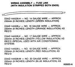
NOTE: Some fuse links shown have an eyelet terminal for a 8mm (5/16 inch) stud
on one end.
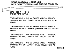
When terminal is not required, use one of the fuse links with
the insulation stripped from both ends.
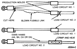
- To service a two-link group when only one link has blown and other link is
not damaged proceed as follows:
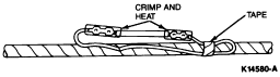
- Cut out blown fusible link (two places).
- Position correct eyelet type service fusible link with bare end to correct
size wire connector and crimp to wire ends. Use Wire Fitting Crimping Tool
T67S-17018-A. Heat splice insulation until tubing shrinks and adhesive flows
from each end of connector.
- To service a fuse link in a multi-feed or single circuit, proceed as
follows:
- Determine which circuit is damaged, its location and cause of the blown
fuse link. If damaged fuse link is one of three fed by a common No. 10- or
12-gauge feed wire, determine specific affected circuit.
- Cut damaged fuse link from wiring harness and discard. If fuse link is one
of three circuits fed by a single feed wire, cut it out of harness at each
splice end and discard.
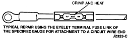
- Identify and procure proper fuse link and connectors for attaching fuse
link to harness.
- Strip wires 7.6mm (5/16 inch) and insert into proper gauge wire connector.
Crimp and heat splice insulation until tubing shrinks and adhesive flows from
each end of connector.
- To replace any fuse link on a single circuit in a harness, cut out damaged
portion. Strip approximately 12.7mm (1/2 inch) of insulation from two wire ends
and attach correct size fuse link to each wire end with proper gauge wire
connectors. Crimp and heat splice insulation until tubing shrinks and adhesive
flows from each end of connector.
- To service any fuse link which has an eyelet terminal on one end such as
the charging circuit, proceed as follows:
- Cut off open fuse link behind weld, strip approximately 12.7mm (1/2 inch)
of insulation from cut end, and attach appropriate new eyelet fuse link to cut
stripped wire with an appropriate size connector.
- Crimp and heat splice insulation until tubing shrinks and adhesive flows
from each end of connector.
DO NOT MISTAKE A RESISTOR WIRE FOR A FUSE LINK. The
resistor wire is generally longer and has print stating
"Resistor—do not cut or splice."
When attaching a No. 16-, 18- or 20-gauge fuse link to a
heavy gauge wire, always double the stripped wire end of the fuse link before
inserting and crimping it into the wire connector for positive wire
retention.
NOTE: If the damaged fuse link is between two splices (weld points in the
harness), cut out damaged portion as close to splices as possible.
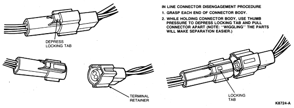
The following illustrations show typical electrical connectors and their
disengagements.
In-Line Connectors
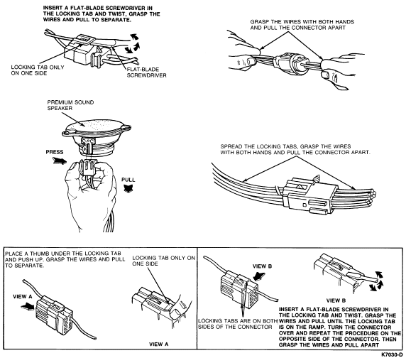
Component Connectors
In-Line Connector, Submersible