Section 12-00: Climate Control SystemŚService | 1993 Mustang Workshop Manual |
DIAGNOSIS AND TESTING
Heater Core Leak Test
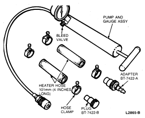
Tools Required:
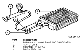
- Rotunda Radiator/Heater Core Pressure Tester 021-00012.
Inspection
- Inspect for visible evidence of coolant leakage at the hose to heater core
attachments. A coolant leak at the hose could follow the heater core tube to
the core and appear as a leak in the heater core.
- Check the system for loose heater hose clamps. The clamps should be
tightened to 1.7-2.4 Nm (15-21 lb-in).
- If leakage is found, and hose clamps are over-tightened remove hose and
check heater core tube for damage. Service damaged or deformed heater tube,
replace clamp and tighten to specification. An over-tightened clamp may cause
leakage at hose connection.
Pressure Test
NOTE: Due to space limitations in the engine compartment, a bench test is
recommended for heater core pressure testing.
- Drain the coolant from the cooling system.
- Disconnect the heater hoses from the heater core tubes.
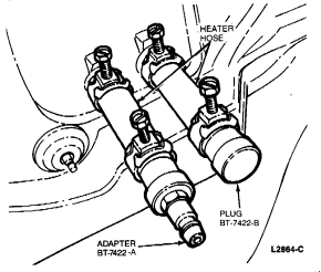
- Install a short piece of heater hose, approximately 101mm (4 inches) long,
on each heater core tube.
- Fill the heater core and hoses with water and install Plug BT-7422-B and
Adapter BT-7422-A from Rotunda Pressure Tester 021-00012 or equivalent in the
hose ends. Secure the hoses, plug and adapter with hose clamps.
Heater Hose with Plug and Adapter Installed
- Attach the pump and gauge assembly from Rotunda Pressure Tester 021-00012
or equivalent to the adapter.
Rotunda Pressure Tester 021-00012 with Heater Hose and Clamps
- Close the bleed valve at the base of the gauge and pump 207 kPa (30 psi) of
air pressure into the heater core.
Rotunda Pressure Tester 021-00012 Installed for Pressure Test
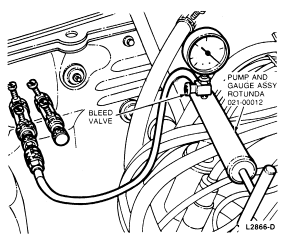
- Observe the pressure gauge for a minimum of three minutes. The pressure
should not drop.
- If the pressure does not drop, no leaks are indicated.
- If the pressure drops, check the hose connections to the core tubes for
leaks. If the hoses do not leak, remove the heater core from the vehicle and
test the core as outlined.
Bench Test
- Remove heater core from heater case.
- Drain all coolant from the heater core.
- Connect the 101mm (4 inch) test hoses with plug and adapter to the core
tubes. Then, connect the air pump and gauge assembly to the adapter.
Heater Core Bench Test (Typical)
- Apply 207 kPa (30 psi) of air pressure to the heater core with
Rotunda Pressure Tester 021-00012 or equivalent, and submerge the core in water.
- If a leak is observed, service or replace the heater core as necessary.
HEATER AND DEFROSTER DIAGNOSIS
| Condition | Possible Source | Action |
|---|
- Air Comes Out of Defroster Outlet in Any Function Selection Lever Position
|
- Vacuum system (indicates a very bad leak).
|
- Listen for vacuum system leak. Look for disconnected vacuum hose
connector. Use hand operated vacuum pump, and check vacuum motors for diaphragm
leak. Also check for leaking vacuum selector valve on control assembly, check
valve, and leaking vacuum reservoir tank. Service hoses, or replace components
as required.
|
- Cowl Ventilation System Leaks Air When in OFF Position
|
- Outside air door not properly sealing in OFF position (heater only,
outside/recirc door if manual A/C-heater).
|
- Check operation of outside air door for proper seal, kinked, or binding
door. Service as required.
|
- Blower Does Not Operate Properly
|
|
- Run a No. 10 gauge jumper wire directly from the (grounded) negative
battery terminal to the negative lead (black wire) of blower motor. If the
motor runs, the problem must be external to the motor. If the motor will not
run, check the ground connection for good electrical contact. If this
connection is good, the motor is inoperative and should be replaced.
|
| |
|
- Check continuity of resistors for opens or check thermal limiter for
continuity, if so equipped. (A blown thermal limiter will allow motor operation
on HI blower only. Service or replace as required.
|
| |
|
- Check for proper installation of harness connector terminal connectors.
- Check wire-to-terminal continuity.
- Check continuity of wires in harness for shorts (a short to ground will
cause motor to operate with no control over the motor), open, abrasion, etc.
- Service as required.
|
| |
|
- Check blower switch(es) for proper contact. Replace switch(es) as
required.
|
| |
- Function selector switch.
|
- Check function selector switch for proper contacts. Replace if required.
|
- Air Flow Changes Direction When Vehicle is Accelerated
|
|
- Check vacuum system with hand vacuum pump from control assembly
connector. Service tubing, or replace damaged components as required.
|
- Insufficient, Erratic, or No Heat or Defrost
|
- Kinked, clogged, collapsed, soft, swollen, or decomposed engine cooling
system or heater system hoses.
|
- Replace damaged hoses and back-flush engine cooling system. Then
back-flush heater system, until all particles have been removed.
|
| |
|
- Check cowl air inlet for leaves, foreign material, etc. Remove as
required.
|
- Insufficient, Erratic, or No Heat or Defrost
|
Low radiator coolant due to:
- Coolant leaks.
|
- Check radiator cap pressure.
- Fill to level. Pressure test for engine cooling system and heater system
leaks. Service as required.
|
| |
|
- Remove bugs, leaves, etc, from radiator or condenser fins.
- Check for: Loose fan belt, sticking thermostat, incorrect ignition
timing, water pump impeller damage, restricted cooling system.
- Service as required.
|
| |
|
- Replace if cracked or worn and/or adjust belt tension.
|
| |
|
- Feel heater outlet hose when engine is at operating temperature. If it
is too hot to hold, thermostat is OK. If not too hot to hold, replace
thermostat.
|
| |
- Plugged or partially plugged heater core.
|
- Clean and backflush engine cooling system and heater core.
|
| |
- Loose or improperly adjusted temperature cable.
|
|
| |
- Vacuum hoses crossed, collapsed, or kinked (if applicable).
|
- Check to see if door vacuum motors respond properly to movements of the
Function Selector Lever. Visually check vacuum hoses, and service as required.
|
| |
- Air flow control doors sticking or binding.
|
- Check to see if door vacuum motors respond properly to movements of
Function Selector Lever. If hesitation in movement is noticed, disconnect
vacuum motor arm from door crank arm, and move crank arm by hand. Service
sticking or binding door as required.
|
| |
- Vacuum motor hose leaks (if applicable).
|
- Disconnect multiple vacuum connector from back of Control Assembly.
Check each connector opening with hand operated vacuum pump. If one line leaks
vacuum, test motor by itself before replacing. (Be careful of vacuum hoses that
operate two motors at same time.) Service vacuum hose(s), or replace vacuum
motor as required.
|
Checking For Air Conditioning Leaks
Tools Required:
- Rotunda Electronic Leak Detector 055-00014 or 055-00015
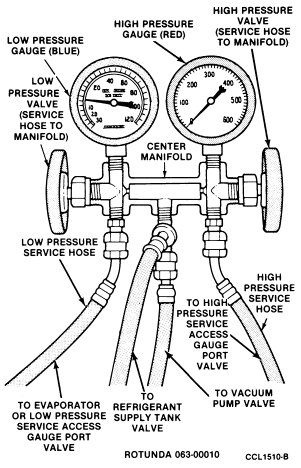
Attach the manifold gauge set. Leave both manifold gauge valves at the
maximum clockwise (closed) position. Both gauges should show approximately
413-551 kPa (60-80 psi) at 24°C (75°F) with
engine not running. If very little or no pressure is indicated, leave the
vacuum pump valve closed, open the Refrigerant-12 cylinder valve and set the
low-pressure (suction) manifold gauge valve to the counterclockwise position.
This opens the system to cylinder pressure.
 WARNING: GOOD VENTILATION IS NECESSARY IN THE AREA WHERE A/C LEAK TESTING IS TO
BE DONE. IF THE SURROUNDING AIR IS CONTAMINATED WITH REFRIGERANT GAS, THE LEAK
DETECTOR WILL INDICATE THIS GAS ALL THE TIME. ODORS FROM OTHER CHEMICALS SUCH
AS ANTIFREEZE, DIESEL FUEL, DISC BRAKE CLEANER OR OTHER CLEANING SOLVENTS CAN
CAUSE THE SAME CONCERN. A FAN, EVEN IN A WELL VENTILATED AREA, IS VERY HELPFUL
IN REMOVING SMALL TRACES OF AIR CONTAMINATION THAT MIGHT AFFECT THE LEAK
DETECTOR.
WARNING: GOOD VENTILATION IS NECESSARY IN THE AREA WHERE A/C LEAK TESTING IS TO
BE DONE. IF THE SURROUNDING AIR IS CONTAMINATED WITH REFRIGERANT GAS, THE LEAK
DETECTOR WILL INDICATE THIS GAS ALL THE TIME. ODORS FROM OTHER CHEMICALS SUCH
AS ANTIFREEZE, DIESEL FUEL, DISC BRAKE CLEANER OR OTHER CLEANING SOLVENTS CAN
CAUSE THE SAME CONCERN. A FAN, EVEN IN A WELL VENTILATED AREA, IS VERY HELPFUL
IN REMOVING SMALL TRACES OF AIR CONTAMINATION THAT MIGHT AFFECT THE LEAK
DETECTOR.
Check all systems connections, the compressor head gasket and shaft seal
for leaks, using a good leak detector. Pass leak detector along underside of
all points being checked. Refrigerant is heavier than air and will show most
readily in those locations.
Manifold Gauge Set
Use Rotunda Electronic Leak Detector 055-00014, 055-00015 or equivalent.
Leak DetectorŚElectronic 055-00014 or 055-00015
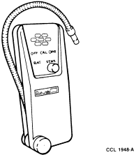
The electronic leak detector is operated by moving the control switch to
the ON position. The detector automatically calibrates itself when it is turned
on. Move the probe at approximately 25mm (1 inch) per second in the suspected
area. When escaping refrigerant gas is located, the ticking/beeping signal will
increase in ticks/beeps per second. If the gas is relatively concentrated the
signal will be increasingly shrill. Follow the instructions included with the
detector to improve handling and operating techniques.
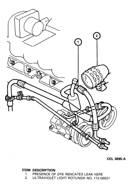
Leak Tracer Dye
Tools Required:
- Rotunda Fluoro-Lite Tracer Dyes 112-00027
- Rotunda A/C Tracer Dye Injector 112-00028
- Rotunda Ultraviolet Lamp 112-00021
Rotunda Fluoro-Lite 112-00027 or equivalent may also be used to detect
refrigerant leaks. With the tracer dye in the system, use Rotunda Ultraviolet
Lamp 112-00021 or equivalent to find the leak or leaks. The tracer dye will
glow a bright yellow/green color at the point of refrigerant leakage when the
light is directed toward the leak. If the system pressure is above 60 psi,
there is no need to add refrigerant to the system for this operation.
Rotunda Fluoro-Lite tracer dye may be introduced into the A/C system
using Rotunda A/C Tracer Dye Injector 112-00028 or equivalent. Inject the dye
and check for leaks as follows:
Tracer Dye Injector 112-00028
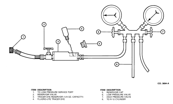
- Close valve on dye injector.
- Connect hose end of dye injector to system low pressure gauge port valve
and tighten it securely.
- Close both valves on manifold gauge set and connect center hose to a
charging cylinder. Leave center hose loose at the manifold gauge set .
Momentarily open charging cylinder valve to purge air out of center hose, then
tighten center hose at manifold gauge set connection. Close valve on charging
cylinder.
- Connect manifold gauge set low pressure hose to dye injector, leaving
connection at the manifold gauge set loose.
- Open dye injector valve to allow A/C system pressure to purge air from dye
injector reservoir and low pressure hose to manifold gauge set. Tighten hose
connection at manifold gauge set. Close valve on dye injector.
- Remove reservoir cap from the top of dye injector and fill reservoir with
1/4 ounce of Fluoro-Lite tracer dye.
CAUTION: Do not overfill.
- Replace reservoir cap. Tighten securely.
- Open valve on charging cylinder, then open manifold gauge set low pressure
valve. Open valve on the dye injector for 5 to 10 seconds to allow dye to be
forced into A/C system. Close dye injector valve. Close manifold gauge set low
pressure valve and valve on the charging cylinder.
- Start engine and operate the A/C system at MAX to stabilize the system
(approximately 10-15 minutes). Smaller leaks will require considerably more
time for the dye to become evident.
- Shut OFF engine.
- Disconnect all hoses slowly to dissipate any residual refrigerant pressure
that may be present.
- Using Rotunda Ultraviolet Lamp 112-00021 or equivalent (Fig. 21), check
system for leaks. The tracer dye will glow a bright yellow/green when
ultraviolet light hits it.
NOTE: Periodically lubricate dye injector reservoir valve stem with refrigerant
oil.
Ultraviolet Lamp 112-00021