Remove turn signal, and wash/wipe switches, upper steering shaft bearing,
and lock cylinder housing.
Remove the U-joint assembly, and pull steering shaft assembly out of the
outer tube from the top of the tube.
Scribe a mark on upper steering shaft where upper and lower steering shaft
sections form a joint line.
Separate the upper and lower steering shaft sections.
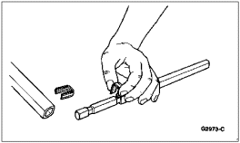
Remove and discard the two insulator clips.
Installation
Install two new steel insulator clips in the grooves on the steering column
upper shaft. Both clips must be installed facing the same
direction.
Lubricate the lower 152mm (6 inch) of the steering column upper shaft with
a liberal amount of Premium Long-Life Grease XG-1-C (ESA-M1C75-B) or equivalent.
Place the steering column lower shaft in a vise, and install the upper
shaft into the lower shaft to the scribed mark on the steering column lower
shaft.
Insert the steering shaft into the outer tube from the top of the tube, so
that the lower end of the shaft protrudes through the lower bearing.
Fasten lock cylinder housing on the outer tube flange bracket loosely.
Install the upper steering shaft bearing, snap ring, and retainer plate.
Install the steering shaft to the lock cylinder housing. Install the two
bolts to secure the housing to the outer tube.