Section 11-02: Steering System, Power
1993 Mustang Workshop Manual
DISASSEMBLY AND ASSEMBLY

Tie Rod Ends, Bellows and Ball Joint Sockets

Tools Required:


Disassembly

  1. Install two long bolts and washers through the bushings, and attach to Bench Mounted Holding Fixture T57L-500-B.
  1. Loosen the jam nuts on the outer ends of the tie rods adjacent to the tie rod ends, and remove the ends and jam nuts.

     CAUTION: Use care not to damage the bellows as internal damage to rack may result.

  1. Remove the four clamps retaining the bellows to the gear housing and the tie rods. Discard the clamps if damaged or excessively corroded.
  1. Remove the bellows along with the breather tube.

    NOTE: For units equipped with rivets in place of the coiled pins, perform Steps 7 and 8:
  1. If pinion requires removal, remove pinion before proceeding as outlined.
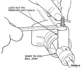
  1. Using Locknut Pin Remover D81P-3504-N or equivalent, remove coiled lockpins from inner tie rod ball joints.


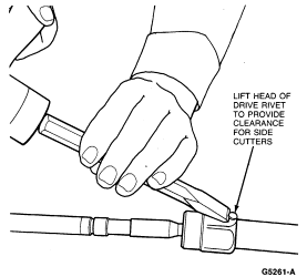
  1. With a sharp chisel, gently tap around rivet head so it lifts away from ball joint. Use caution so the center pin is not sheared off.


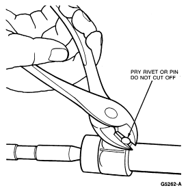
  1. Use side cutters to pry out drive pin.


  1. If pinion was not removed in Step 5, remove housing from the holding fixture and lay on the bench before proceeding. This prevents gear teeth damage from rack twisting when removing the tie rods in Step 10.

    NOTE: Some gear assemblies may contain one or two rack travel restrictors on each side of the rack. The restrictors are split nylon washers and, if required, can easily be removed from the rack following Tie Rod Removal. Restrictors may be reused unless heavily worn.
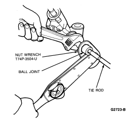
  1. Position rack so that several rack teeth are exposed. Hold rack with an adjustable wrench on the end teeth only, while loosening ball joint nuts with Nut Wrench T74P-3504-U.


Assembly

  1. If pinion is installed, turn gear against or near LH stop and hold rack with adjustable wrench nearest the rack end. Tighten each ball joint assembly separately using Nut Wrench T74P-3504-U to 75-88 Nm (55-65 lb-ft).
  1. If pinion was removed, hold one ball joint nut with a 1-5/16 inch open-end or box wrench while tightening the other nut to 75-88 Nm (55-65 lb-ft) with Nut Wrench T74P-3504-U. Both ends are tightened simultaneously by this method.
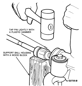
  1. Support the ball housing with a wood block. Install new roll pins in the tie rod ball housing by tapping lightly with a plastic hammer.


  1. If pinion was removed, install pinion as outlined.
  1. Thoroughly clean the rack and housing bore of any foreign material. Any abrasive material is extremely harmful to the high-pressure oil seals.
  1. Apply Steering Gear Grease C3AZ-19578-A (ESW-M1C87-A) or equivalent to groove in the rods where the bellows clamp to the tie rod. This allows for toe-in adjustment without twisting the bellows.
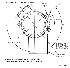
  1. Install bellows and breather tube. Install clamps retaining the bellows to the gear housing and tighten to 2.3-3.4 Nm (1.7-2.5 lb-ft). Position bellows, tube and clamps.


  1. Install new clamps retaining bellows to tie rods.
  1. Install the jam nuts on the tie rods.
  1. Apply Disc Brake Caliper Slide Grease D7AZ-19590-A (ESA-M1C172-A) or equivalent to tie rod threads.
  1. Install tie rod outer ends on the tie rods.