Section 07-01B: Transmission, Automatic—AOD
1993 Mustang Workshop Manual
DISASSEMBLY AND ASSEMBLY

Transmission, Assembly

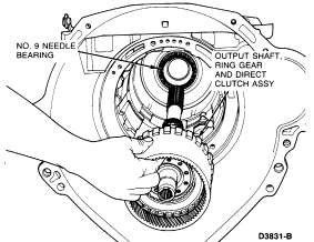
  1. Install the output shaft needle bearing No. 9 in the transmission case.
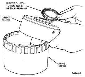
  1. Install the No. 8 needle bearing to the back of the direct clutch drum.


  1. Install direct clutch on output shaft.
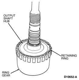
  1. Install output shaft ring gear over top of direct clutch onto output shaft hub. Lock into place with snap ring.


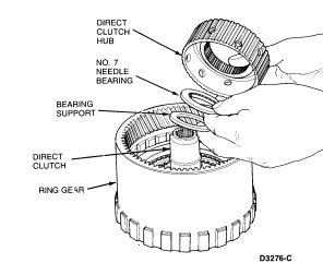
  1. Install the bearing support, No. 7 needle bearing and direct clutch hub in the direct clutch.


  1. Install the output shaft, the ring gear and the direct clutch as an assembly.


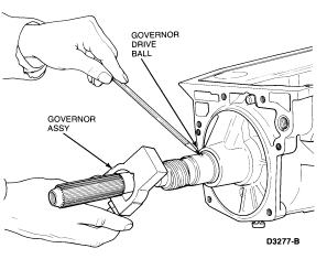
  1. Install the governor drive ball and the governor assembly.


    NOTE: Ensure that the face of the governor body is about flush with the counterweight. The cover and retaining screws must face toward the case (forward).
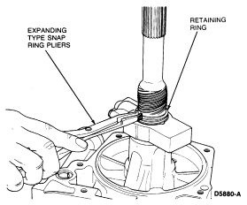
  1. Install the governor retaining ring.


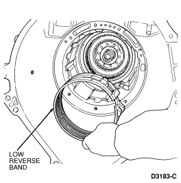
  1. Install the low/reverse band.


    NOTE: Ensure the band is seated on the anchor pins.
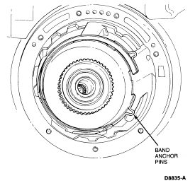


    NOTE: When properly installed, the center of the band actuating rod seat can be seen through the servo piston bore.
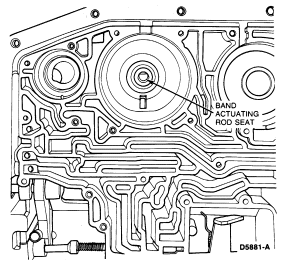
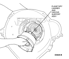


  1. Install the center support and planetary assembly. Rotate the output shaft, if necessary, to align the planet carrier splines with the direct clutch hub splines.


    NOTE: The planetary carrier and center support assembly cannot be installed unless the notch cut in the center support is aligned with the overdrive band anchor pin.
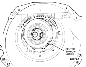


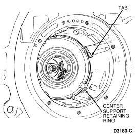
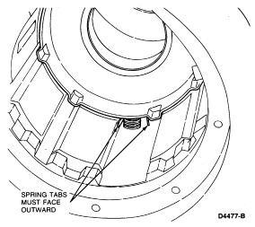
  1. Install the center support anti-clunk spring using a hammer handle or wooden dowel.

    NOTE: Spring tabs must face outward.


  1. Install the center support retaining ring.


  1. To determine the correct length of the low/reverse servo piston, proceed as follows:
    1. Lubricate the low/reverse piston seal to facilitate assembly and to prevent damage to the seal.
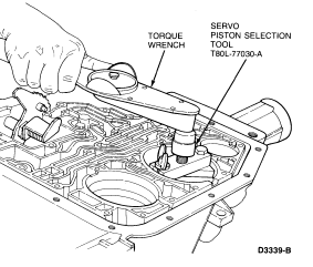
    1. Install the low/reverse servo piston and return spring. Do not install the piston cover or retaining ring.
    1. Install Servo Piston Selection Tool T80L-77030-A. Tighten the band apply bolt on Servo Piston Selection Tool T80L-77030-A to 5.6 Nm (50 lb- in).


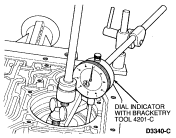
    1. Attach Dial Indicator with Bracketry TOOL-4201-C or equivalent and position the indicator stem on the flat portion of the piston. Zero the dial indicator.


    1. Thread the bolt out of the selector tool until the piston stops against the bottom of the tool.
    1. Read the amount of piston travel on the dial indicator.
      • If the travel is 2.845-6.020mm (0.112-0.237 inch), the piston length is within specification.
      • If the travel is not within specification, selective pistons are available in the following lengths:
      • ID
      • 74.56mm (2.936 inch) 1 groove
      • 75.92mm (2.989 inch) 2 grooves
      • 77.29mm (3.043 inch) 3 grooves
      • Length of rod measured from piston surface to end of rod.
      • Select the proper rod to bring the servo piston travel within specification.
    1. Lubricate the cover seal to facilitate assembly and to prevent damage to the seal.
    1. Remove the servo selection tool and dial indicator.
    1. Install the servo cover and retaining ring.
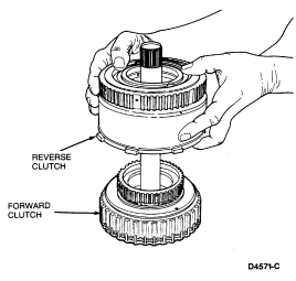
  1. Install the reverse clutch on the forward clutch.


    NOTE: Ensure the No. 2 needle bearing is in position.
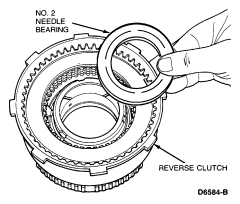


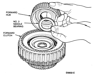
  1. Install the No. 3 needle bearing and forward clutch hub in the forward clutch.


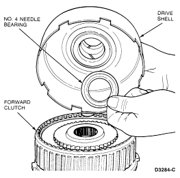
  1. Position the No. 4 needle bearing on the forward clutch hub and install the drive shell.


  1. Install the No. 5 needle bearing and forward sun gear on the drive shell.


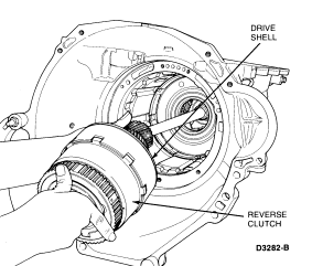
  1. Install the drive shell, forward clutch and reverse clutch as an assembly. Rotate the output shaft, as necessary, to aid the engagement of the sun gear with the planetary gears.


  1. Install the overdrive band. Make sure the band anchor is properly positioned on the anchor pin.


  1. Lubricate the overdrive servo cover seals to facilitate assembly and to prevent damage to the seal.
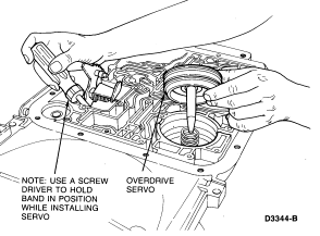
  1. Install the overdrive servo.


  1. With the overdrive servo installed, inspect the apply pin and band for proper position and engagement. If the band anchor and apply pin are not properly engaged, remove the servo and reposition the band as necessary.


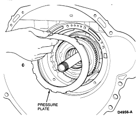
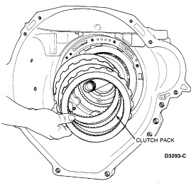
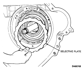
  1. Install the intermediate clutch pack components in the following order:
    1. Pressure plate.


    1. Clutch pack.


    1. Selective steel plate.


      NOTE: Maintain a downward pressure on the clutch pack while measuring depth.

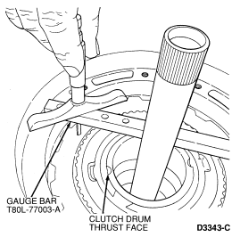
  1. Measure the intermediate clutch clearance using a Depth Micrometer D80P-4201-A and Gauge Bar T80L-77003-A or equivalent. Set the end play tool across the pump case mounting. Locate the micrometer end play gauge bar and read the depth. The depth at the intermediate clutch separator plate is 41.5-41.8mm (1.634-1.636 inches).

    Check the clearance again 180 degrees opposite to ensure the average depth is within tolerance.

    If the depth is not within tolerance, the following size selective steel separator plates are available:

    Install the correct plate and check the clearance.
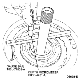


  1. Position the Depth Micrometer D80P-4201-A on Gauge Bar T80L-77003-A so that the depth is measured at the reverse clutch drum thrust face. Check the end play 180 degrees opposite to determine the average depth. The following chart shows the proper selective thrust washer for various depth measurements.

    Depth Washer No. Washer Size Washer Color
    37.668-38.113mm
    (1.483-1.500 inch)
    1 1.27-1.37mm
    (0.050-0.054 inch)
    Green
    38.114-38.540mm
    (1.501-1.517 inch)
    2 1.72-1.82mm
    (0.068-0.072 inch)
    Yellow
    38.541-38.970mm
    (1.518-1.534 inch)
    3 2.15-2.16mm
    (0.085-0.089 inch)
    Natural
    38.971-39.408mm
    (1.535-1.551 inch)
    4 2.59-2.67mm
    (0.102-0.106 inch)
    Red
    39.409-39.827mm
    (1.552-1.568 inch)
    5 3.02-3.12mm
    (0.119-0.123 inch)
    Blue


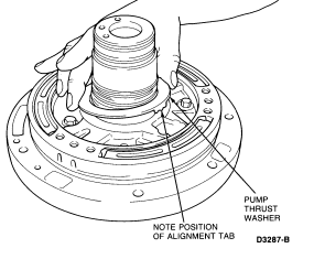
  1. Install the selective washer determined in Step 20 on the pump. Use petroleum jelly to hold it in place.


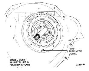
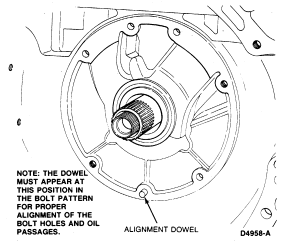
  1. Install pump alignment dowel. The alignment dowel can be fabricated by removing the head from a M8-1.25 bolt. Install the dowel only a few threads in the position shown.
  1. Install a new pump gasket.


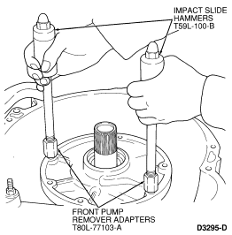
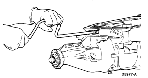
  1. Using Impact Slide Hammer T59L-100-B and Pump Puller Adapters T89T-70010-A, lower the pump assembly into the case.


    NOTE: The dowel must appear at this position in the bolt pattern for proper alignment of the bolt holes and oil passages.


    NOTE: Clean seven retaining bolts with a wire brush to remove loose particles of sealant. Apply a coating of Threadlock and Sealer E0AZ-19554-AA (ESE-M4G204-A) or equivalent, to bolt threads before reinstallation.
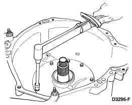
  1. Remove the alignment dowel and install the seven pump retaining bolts. Alternately tighten the bolts a few turns at a time to draw the pump into the case. Tighten the retaining bolts to 22-27 Nm (16-20 lb-ft).


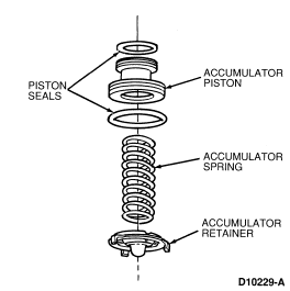
  1. Assemble the 2-3 accumulator.


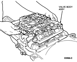
  1. Install a new valve body gasket and the valve body assembly.

    NOTE: Ensure the manual and throttle levers are properly positioned before installing the valve body retaining bolts.
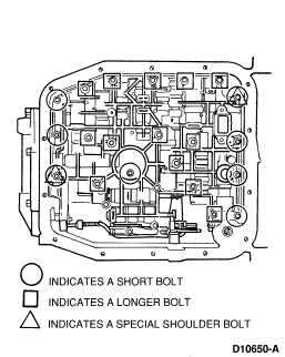


  1. Install two shoulder bolts.


    NOTE: Two different length bolts are used. The shorter bolts are used at the four front, one center and three rear locations. Refer to the illustration.
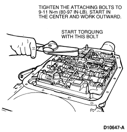
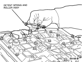
  1. Loosely install valve body retaining bolts using an 8mm socket, starting at the center and working outward. Tighten bolts to 9-11 Nm (80-97 lb-in).


  1. Install the detent spring and roller assembly (long bolt). Tighten the bolts to 9-11 Nm (80-97 lb-in).


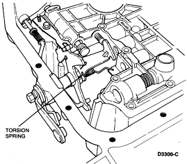
  1. Position the TV lever torsion spring against the separator plate V-notch. This spring pushes the throttle lever in the direction of wide-open throttle.


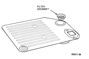
  1. Install the filter grommet.


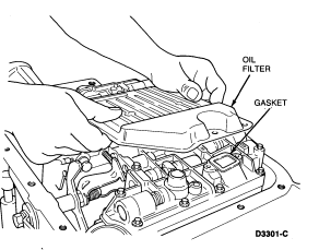
  1. Install a new filter gasket and the filter on the valve body.


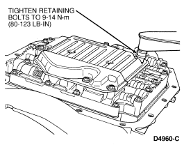
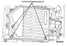
  1. Install the filter retaining bolts. Tighten the retaining bolts to 9-14 Nm (80-123 lb- in).


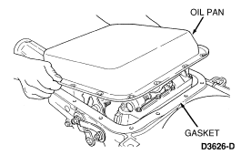
  1. Install a new pan gasket and install the oil pan using a 10mm socket. Tighten the retaining bolts to 8-13.5 Nm (71-119 lb-in).


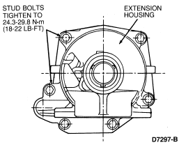
  1. Clean the mounting surface on the transmission and on the extension housing. Remove any sealant from the bolts and the case bolt holes. Install stud bolt in hole 6. Position a new gasket on the transmission. Coat bolts with Threadlock and Sealant E0AZ-19554-AA (ESE-M4G204-A) or Pipe Sealant with Teflon® D8AZ-19554-A (ESG-M4G194-A and ESR-M18P7-A) or equivalent. Tighten the retaining bolts to 24.3-29.8 Nm (18-22 lb-ft).


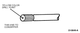
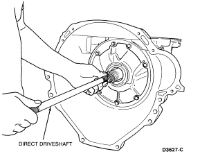
  1. Install the direct driveshaft.

    NOTE: Some models may have a yellow drill point on one end of the direct driveshaft. The end having the yellow drill point must face the converter.


Extension Housing Bushing

Tools Required:


Installation
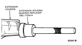
  1. Install the extension housing bushing using Extension Housing Bushing Replacer T80L-77034-A.
  1. Install the extension housing seal as outlined.


Extension Housing Seal

Tools Required:


Installation

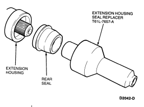
Install the extension housing seal using Extension Housing Seal Replacer T61L-7657-A.