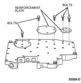
NOTE: When removing the 11 bolts, note the location of the two shoulder bolts. They must be installed in the same locations when assembling the valve body.
Section 07-01B: Transmission, Automatic—AOD | 1993 Mustang Workshop Manual |
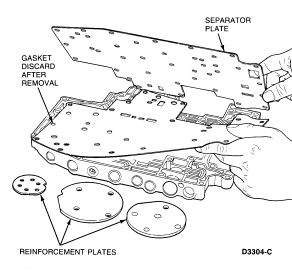
Disassembly
NOTE: When removing the 11 bolts, note the location of the two shoulder bolts. They must be installed in the same locations when assembling the valve body.

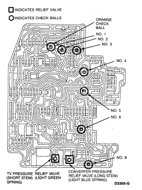
NOTE: The check balls are numbered one through eight. Check ball number seven was eliminated in a previous production year. There are a total of seven check balls.
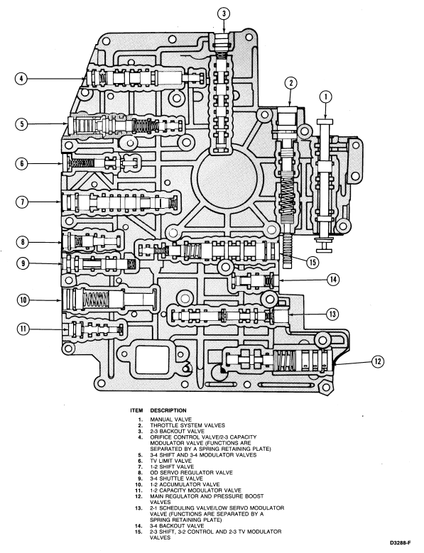
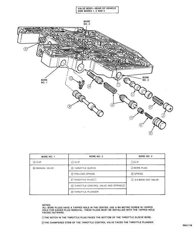
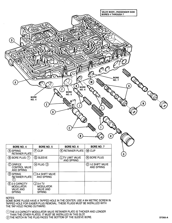
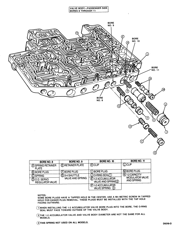
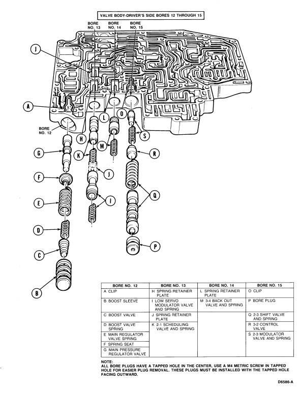
Assembly
Note the location of the orange ball. This ball is larger than the others and must be positioned as shown.
NOTE: The check balls are labeled one through eight. Check ball seven was eliminated in a previous production year. There are a total of seven check balls.

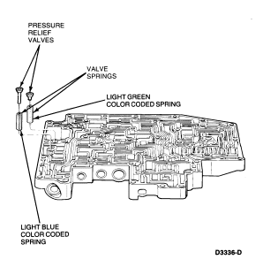
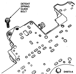
 CAUTION: The two shoulder bolts must be installed at alignment holes only.
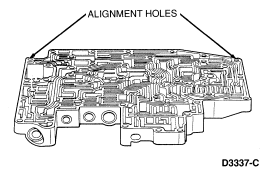
 CAUTION: Do not use a shoulder bolt at the detent spring guide or damage to
valve body casting will result.
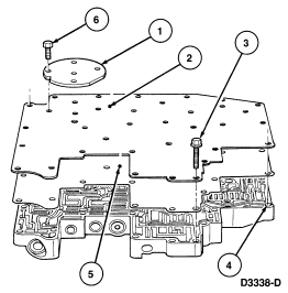
| Item | Part Number | Description |
|---|---|---|
| 1 | 7F282 | Reinforcement Plate |
| 2 | 7A008 | Separator Plate |
| 3 | — | Detent Spring Guide Bolt |
| 4 | — | Alignment Hole |
| 5 | 7D100 | Separator Gasket |
| 6 | — | Bolts |
