Section 07-01B: Transmission, Automatic—AOD | 1993 Mustang Workshop Manual |
DISASSEMBLY AND ASSEMBLY
Subassemblies
Case Bushing
Tools Required:
- Thread Impact Slide Hammer T50T-100-A
- Rear Case Bushing Replacer T80L-77110-A
- Seal Remover TOOL-1175-AC
Removal
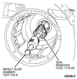
To remove the transmission case bushing, use Thread Impact Slide Hammer
T50T-100-A and Seal Remover TOOL-1175-AC or equivalent.
Installation
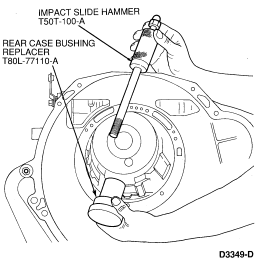
- Position the replacement bushing on Rear Case Bushing Replacer T80L-77110-A
and install in the bushing bore through the front of the case.
- Thread Impact Slide Hammer T50T-100-A into the bushing installer through
the back of the case and install the bushing.
Pump Seal
Tools Required:
- Front Pump Seal Replacer T63L-77837-A
- Impact Slide Hammer T59L-100-B
- Seal Remover TOOL-1175-AC
Removal
Remove the pump seal using Seal Remover TOOL-1175-AC and Impact Slide
Hammer T59L-100-B.

Installation
Install the seal using Front Pump Seal Replacer T63L-77837-A.

Pump and Intermediate Clutch Piston
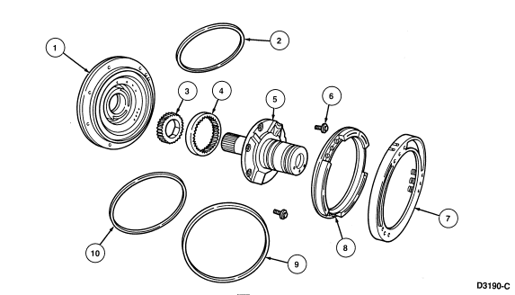
| Item |
Part Number |
Description |
|
1
|
7A103
|
Front Pump Body
|
|
2
|
7D441
|
Front Pump O-Ring Seal
|
|
3
|
7C010
|
Front Pump Drive Gear
|
|
4
|
7C011
|
Front Pump Driven Gear
|
|
5
|
7A108
|
Stator Support—Front Pump
|
|
6
|
—
|
Stator Support to Pump Body Bolts
|
|
7
|
7F222
|
Intermediate Clutch Piston Return Spring and Retainer Assy
|
|
8
|
7E006
|
Intermediate Clutch Piston
|
|
9
|
7F224
|
Intermediate Clutch Piston Outer Lip Seal
|
|
10
|
7F225
|
Intermediate Clutch Piston Inner Lip Seal
|
Disassembly
Tools Required:
- Lip Seal Protector T80L-77005-A
- Remove the No. 1 thrust washer.
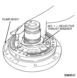
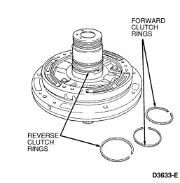
- Remove the four pump seal rings.
The reverse clutch rings are larger than the forward clutch
rings.
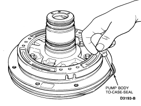
- Remove the pump body-to-case seal and discard.
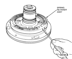
- Remove the spring retainer assembly by carefully dislodging the tabs.
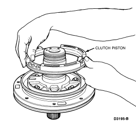
- Remove the clutch piston.
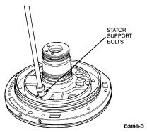
- Remove the five 10mm stator support bolts.
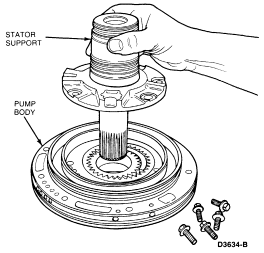
- Remove the stator support.
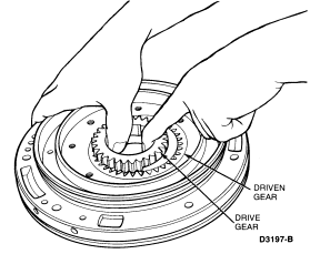
- Remove the drive and driven pump gears from the pump body.
Assembly
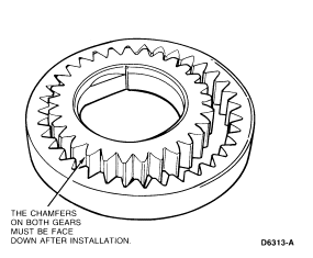
- Install the drive and driven pump gears in the pump body.
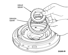
NOTE: Chamfers on both gears face into the pump body.
- Position the stator support to the pump body and install the retaining
bolts. Tighten to 16-22 Nm (12-16 lb-ft).

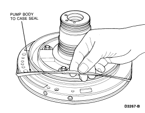
- Install new pump-to-case seal.
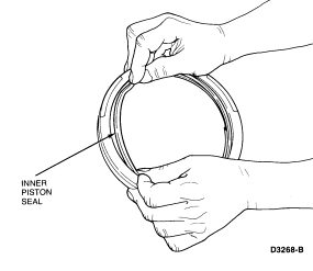
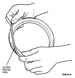
- Install new seals on the clutch piston. Note the direction of the sealing
lip before installation. The lips point away from the spring posts.
- Install the clutch piston as follows:
- Coat the piston seals and the pump body sealing area with petroleum jelly.
- Install the piston in Lip Seal Protector T80L-77005-A.
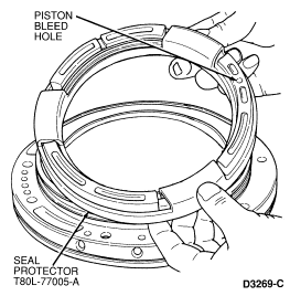
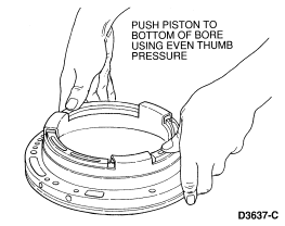
- Install the piston in the pump body and push to the bottom of the bore by
exerting even thumb pressure on the piston.
 CAUTION: The piston bleed hole must be located at 12 o'clock position (toward
top of transmission).
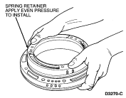
- Snap the spring retainer assembly into place on the pump body. Use even
pressure.
- Install the pump seal rings.
NOTE: Stator support seal rings are the largest rings and are for the reverse
clutch. These rings are closest to the pump. Stator support seal rings are for
the forward clutch. These rings are farthest from the pump body.

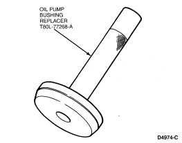
Pump Bushing
Tools Required:
- Oil Pump Bushing Replacer T80L-77268-A
- Oil Pump Bushing Remover T80L-77268-B
Removal
Remove the bushing using Oil Pump Bushing Remover T80L-77268-B.
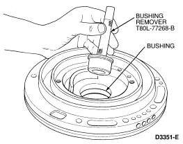
Installation
Install the bushing using Oil Pump Bushing Replacer T80L-77268-A.
Intermediate One-Way Clutch
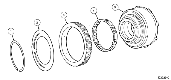
| Item |
Part Number |
Description |
|
1
|
389790-S
|
Intermediate One-Way Roller Clutch Retaining Snap Ring
|
|
2
|
7F262
|
Intermediate One-Way Roller Clutch Retaining Plate
|
|
3
|
7F221
|
Intermediate One-Way Roller Clutch Outer Race
|
|
4
|
7F271
|
Intermediate One-Way Roller Clutch
|
|
5
|
7F215
|
Reverse Clutch Drum
|
Disassembly
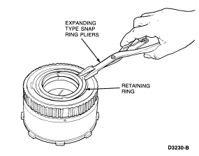
- Using snap ring pliers, remove the clutch retaining ring.
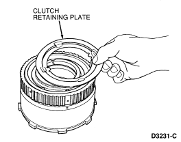
- Remove the clutch retaining plate.
- Remove the clutch outer race by lifting on the race while turning
counterclockwise.
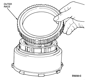
- Carefully lift the one-way clutch from the inner race.
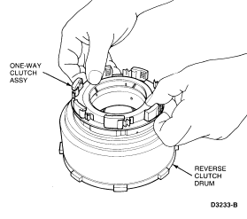
Assembly
- Install one-way clutch to inner race.

- Install clutch outer race on clutch while turning counterclockwise.

- Install clutch retaining plate.

- Using snap ring pliers, install retaining ring.

Reverse Clutch
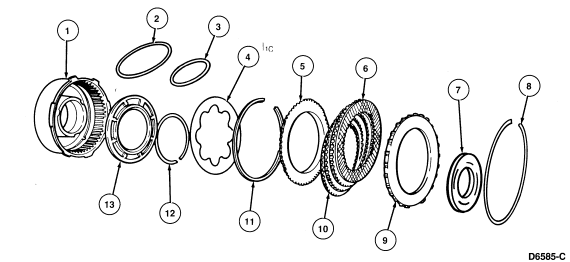
| Item |
Part Number |
Description |
|
1
|
7F215
|
Reverse Clutch Drum
|
|
2
|
7D403
|
Outer Reverse Clutch Piston Seal
|
|
3
|
7D404
|
Inner Reverse Clutch Piston Seal
|
|
4
|
7D405
|
Reverse Clutch Piston Return Spring
|
|
5
|
7B066
|
Reverse Clutch Pressure Plate
|
|
6
|
7E311
|
Reverse Clutch Internal Spline Friction Plates
|
|
7
|
7G008
|
Number Two Needle Bearing
|
|
8
|
7D483
|
Reverse Clutch Selective Retaining Ring
|
|
9
|
7F278
|
Forward and Reverse Clutch Rear Pressure Ring
|
|
10
|
7B442
|
Reverse Clutch External Spline Steel Plates
|
|
11
|
7D406
|
Return Spring Retaining Ring
|
|
12
|
7D256
|
Thrust Ring
|
|
13
|
7E079
|
Reverse Clutch Piston
|
Tools Required:
- Clutch Spring Compressor T65L-77515-A
- Reverse Clutch Outer Seal Protector T80L-77403-A
- Reverse Clutch Inner Seal Protector T80L-77403-B
- Reverse Clutch Spring Compressor Plate T80L-77405-A
- Air Nozzle TOOL-7000-DE
Disassembly
- Remove the No. 2 needle bearing.
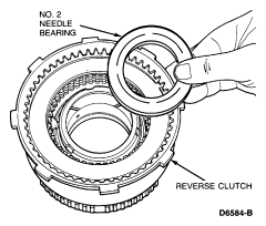
- Remove the clutch pack retaining ring.
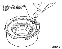
- Remove the clutch pack.
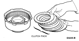
- Remove the wave snap ring using Clutch Spring Compressor T65L-77515-A and
Reverse Clutch Spring Compressor Plate T80L-77405-A.
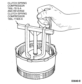
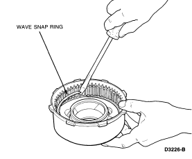
- Remove the piston return spring and the thrust ring.
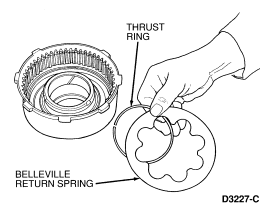
- Remove the clutch piston.
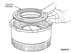
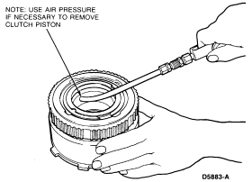
NOTE: To aid removal, it may be necessary to apply air pressure to the drum.
Block the opposite hole with a finger.
Assembly
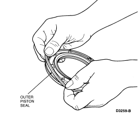
- Install new seals on the clutch piston. Because the seals are square cut,
the direction of installation is not important.
NOTE: The piston check ball must be present and moving freely.
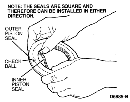
- Install the clutch piston as follows:
- Coat the piston seals and clutch drum sealing area with petroleum jelly.
- Install Reverse Clutch Inner Seal Protector T80L-77403-B and Reverse Clutch
Outer Seal Protector T80L-77403-A in the clutch drum.
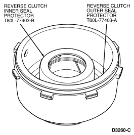
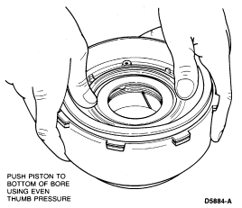
- Coat the piston seals, the clutch drum sealing area and the seal protector
with petroleum jelly.
- Position the piston and push it to the bottom of the drum using even thumb
pressure.
- Install the piston thrust ring and the piston return spring.

- Install the wave snap ring (with points down) using Clutch Spring
Compressor T65L-77515-A and Reverse Clutch Spring Compressor T80L-77405-A.
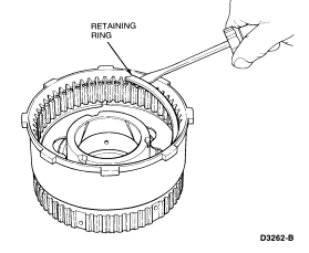

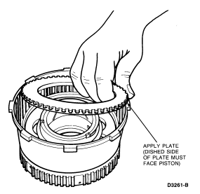
- Install the clutch pack.

NOTE: The apply plate must be installed first. Note that the dished side of the
plate must face the piston.
- Install the clutch pack retaining ring and check the clearance between the
ring and the pressure plate using a feeler gauge. The pressure plate should be
held downward as the clearance is checked.
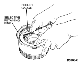
The clearance should be 1.02-1.91mm (0.040-0.075 inch).
If the clearance is not within specification, selective snap
rings are available in the following thicknesses:
- 1.27-1.37mm (0.060-0.064 inch).
- 1.87-1.98mm (0.074-0.078 inch).
- 2.23-2.33mm (0.088-0.092 inch).
- 2.59-2.69mm (0.102-0.106 inch).
Install the correct size snap ring and check the clearance.
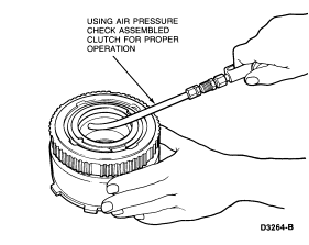
- Check the clutch for proper operation using Air Nozzle TOOL-7000-DE or
equivalent. The clutch should be heard and felt to apply smoothly and without
leakage.
- Install the No. 2 needle bearing.

Forward Clutch
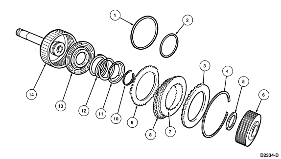
| Item |
Part Number |
Description |
|
1
|
7F227
|
Outer Forward Clutch Piston Seal
|
|
2
|
7F228
|
Inner Forward Clutch Piston Seal
|
|
3
|
7F278
|
Forward and Reverse Clutch Pressure Plate
|
|
4
|
7D483
|
Forward Clutch Pack Retaining Ring
|
|
5
|
7G040
|
Number 3 Needle Bearing
|
|
6
|
7D051
|
Forward Clutch Hub
|
|
7
|
7E311
|
Internal Spline Clutch Plates
|
|
8
|
7B442
|
External Spline Clutch Plates
|
|
9
|
7E085
|
Wave Plate
|
|
10
|
388099
|
Retaining Snap Ring
|
|
11
|
7F229
|
Return Spring Retainer
|
|
12
|
7F230
|
Forward Clutch Piston Return Spring
|
|
13
|
7L140
|
Forward Clutch Piston
|
|
14
|
7F207
|
Forward Clutch Cylinder and Turbine Shaft Assy
|
Tools Required:
- Clutch Spring Compressor T65L-77515-A
- Forward Clutch Outer Lip Seal Protector T68P-7D158-A
- Forward Clutch Inner Lip Seal Protector T80L-77140-A
- Forward Clutch Spring Compressor Extension T80L-77515-A
- Air Nozzle TOOL-7000-DE
Disassembly
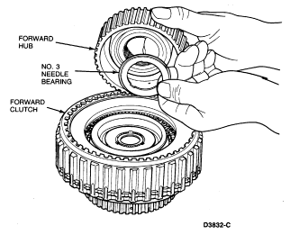
- Remove the clutch hub and No. 3 needle bearing, if not already removed.
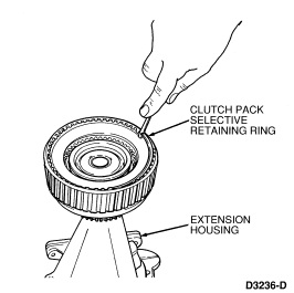
- Remove the clutch pack selective retaining ring.
NOTE: To aid handling, the clutch may set in the extension housing or a 51mm
(2-inch) diameter hole may be cut in the work bench.
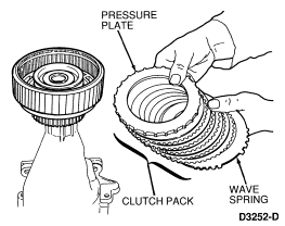
- Remove the clutch pack.
- Compress the piston return spring using Clutch Spring Compressor
T65L-77515-A, and Forward Clutch Spring Compressor Extension T80L-77515-A.
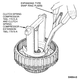
Remove the retaining ring and spring retainer.
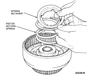
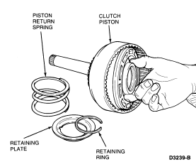
- Remove the clutch piston.
Note the position and direction of the lip seals and remove.
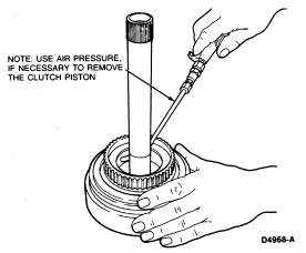
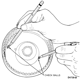
NOTE: Ensure check balls in clutch cylinder are free and clean. Check for
proper seating.
Assembly
- Install new seals on the clutch piston. Note the direction of the sealing
lip before installation.
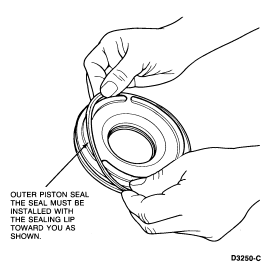
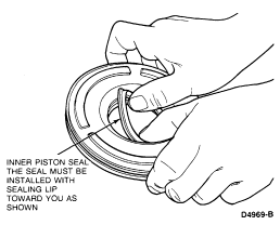
- Install the clutch piston as follows:
- Coat the piston seals and the clutch drum sealing area with petroleum jelly.
- Install the Forward Clutch Inner Lip Seal Protector T80L- 77140-A over the
clutch cylinder hub.
- Install the piston in the Outer Lip Seal Protector, T68P-7D158-A.
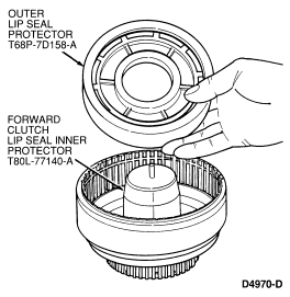
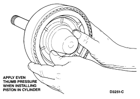
- Position the seal protector and piston in the clutch drum. Push the piston
to the bottom of the drum using even thumb pressure.
- Install the piston return spring, the spring retainer and the retaining
ring.

Compress the piston return spring using Clutch Spring
Compressor T65L-77515-A and Forward Clutch Spring Compressor Extension
T80L-77515-A.

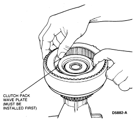
- Install the clutch pack.

NOTE: The wave plate must be installed first.
- Install the clutch pack retaining ring and check the clearance between the
ring and the pressure plate using a feeler gauge.
The pressure plate should be held downward as the clearance is
checked.
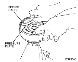
The clearance should be 1.27-2.26mm (0.050-0.089 inch)
If the clearance is not within specification, selective snap
rings are available in the following thicknesses:
- 1.27-1.37mm (0.060-0.064 inch).
- 1.87-1.98mm (0.074-0.078 inch).
- 2.23-2.33mm (0.088-0.092 inch).
- 2.59-2.69mm (0.102-0.106 inch).
Install the correct size snap ring and recheck the clearance.
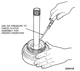
- Check the clutch for proper operation using Air Nozzle TOOL-7000-DE or
equivalent. The clutch should be heard and felt to apply smoothly and without
leakage.
Sun Gear and Drive Shell
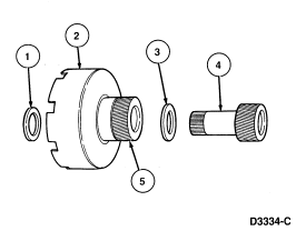
| Item |
Part Number |
Description |
|
1
|
7F244
|
Number 4 Needle Bearing
|
|
2
|
7A019
|
Drive Shell Assy
|
|
3
|
7F244
|
Number 5 Needle Bearing
|
|
4
|
7A399
|
Forward Sun Gear
|
|
5
|
—
|
Reverse Sun Gear Part of 7A019 Drive Shell Assy
|
Disassembly
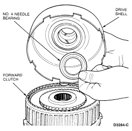
- Remove the No. 4 needle bearing from the drive shell.
- Remove the forward sun gear and No. 5 needle bearing from the drive shell.
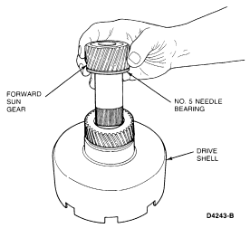
- Remove the No. 5 needle bearing from the forward sun gear.

NOTE: The sun gear and drive shell is assembled as part of the transmission
assembly procedure.
Center Support and Planetary One-Way Roller Clutch
Disassembled View
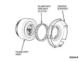
Disassembly
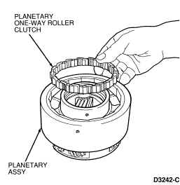
- Remove the center support from the planetary carrier. Rotate the center
support counterclockwise and lift.
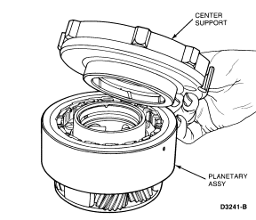
- Carefully remove the planetary one-way roller clutch from the planetary
assembly.
Assembly
- If necessary, assemble the one-way roller clutch.
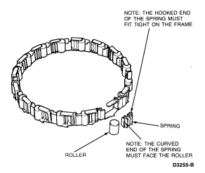
- Install the one-way roller clutch in the planetary carrier.

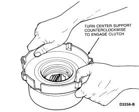
- Install the center support into the one-way roller clutch by rotating the
center support counterclockwise.
Lubricate the clutch races and the clutch assembly with
petroleum jelly to aid in assembly.
Direct Clutch
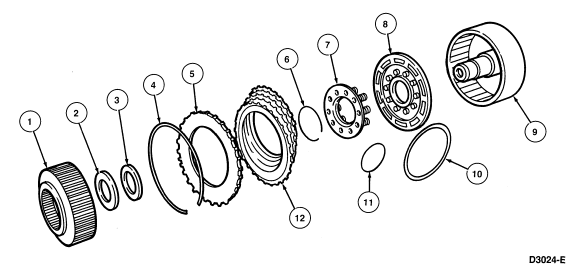
| Item |
Part Number |
Description |
|
1
|
7F236
|
Direct Clutch Hub
|
|
2
|
7F243
|
Number 7 Needle Bearing
|
|
3
|
7F237
|
Bearing Support Thrust Spacer
|
|
4
|
388065-6-7-8
|
Selective Clutch Pack Retaining Snap Ring
|
|
5
|
7B477
|
Direct Clutch Pressure Plate
|
|
6
|
388104
|
Direct Clutch Piston Snap Ring
|
|
7
|
7F235
|
Direct Clutch Return Spring and Retainer Assy
|
|
8
|
7F254
|
Direct Clutch Piston
|
|
9
|
7F283
|
Direct Clutch Cylinder
|
|
10
|
7C000
|
Outer Direct Clutch Piston Seal
|
|
11
|
7F234
|
Inner Direct Clutch Piston Seal
|
|
12
|
7E313 (Internal) 7F238 (External)
|
Direct Clutch Spline Plates
|
Tools Required:
- Clutch Spring Compressor T65L-77515-A
- Direct Clutch Inner Lip Seal Protector T80L-77234-A
- Direct Clutch Outer Lip Seal Protector T80L-77254-A
- Air Nozzle TOOL-7000-DE
Disassembly
- Remove the No. 7 direct clutch hub inner needle bearing.
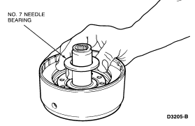
- Remove bearing support.
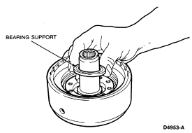
- Remove the clutch pack selective retaining snap ring.
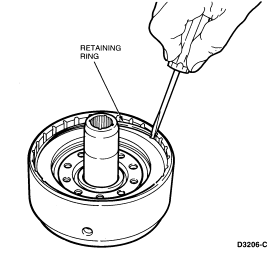
- Remove the clutch pack from the cylinder.
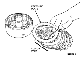
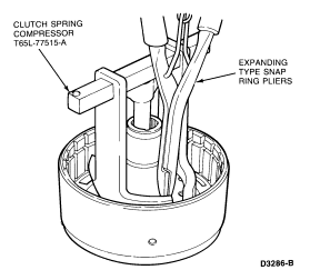
- Using Clutch Spring Compressor T65L-77515-A, compress the piston return
springs. Remove the piston retaining ring using expanding- type snap ring
pliers.
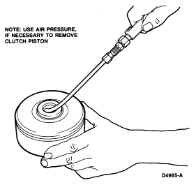
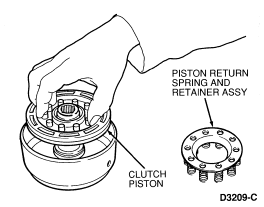
- Remove the spring retainer assembly and piston from the cylinder.
Note the position and direction of the lip seals and then
remove.
Assembly
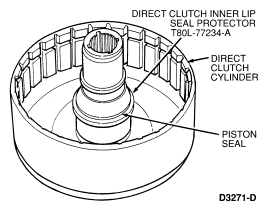
- Install the inner piston seal on the clutch cylinder hub as follows:
- Position Direct Clutch Inner Lip Seal Protector T80L-77234-A over the
clutch cylinder hub.
- Lubricate the seal and the seal protector with petroleum jelly.
- Position the seal over the installer tool with the sealing lip facing down.
- Push the seal down until it snaps off the end of the protector onto the
clutch hub.
- Remove the seal protector from the clutch hub.
- Slide the seal up until it seats in the seal groove.
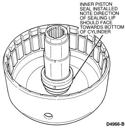
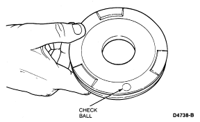
- Inspect the piston check ball. Ensure the ball is present and moves freely.
Check for leakage by performing the Direct Clutch Piston Check Ball Leakage
procedure as outlined.
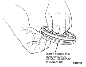
- Install the outer clutch piston seal. Note the direction of the sealing lip
before installation. The lip points away from the spring posts.
- Install the clutch apply piston as follows:
- Coat the piston seals, the clutch cylinder sealing area and the piston
inner seal area with petroleum jelly.
- Install the piston in the Direct Clutch Outer Lip Seal Protector
T80L-77254-A.
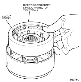
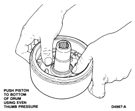
- Position the tool in the clutch drum and push the piston to the bottom of
the drum using even thumb pressure.
- Install the piston spring and retainer assembly and retaining ring using
Clutch Spring Compressor T65L-77515-A.

- Install the clutch pack.

- Install the clutch pack selective retaining ring and check the clearance
between the ring and the pressure plate using a feeler gauge. The pressure
plate should be held downward as the clearance is checked.
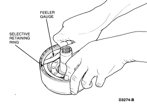
The clearance should be:
- Six Plate 1.57-2.16mm (0.062-0.085 inch).
- Five Plate 1.27-1.80mm (0.050-0.071 inch).
If the clearance is not within limits, selective snap rings
are available in the following thicknesses:
- 1.27-1.37mm (0.050-0.054 inch).
- 1.62-1.72mm (0.064-0.068 inch).
- 1.98-2.08mm (0.078-0.082 inch).
- 2.33-2.43mm (0.092-0.096 inch).
Install the correct size snap ring and check the clearance.
- Check the clutch for proper operation using Air Nozzle TOOL-7000-DE or
equivalent. The clutch should be heard and felt to apply smoothly and without
leakage.

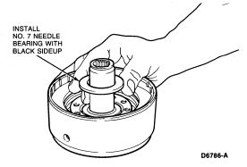
- Install No. 7 needle bearing support.

- Install No. 7 needle bearing (black side up).
Output Shaft
Disassembled View
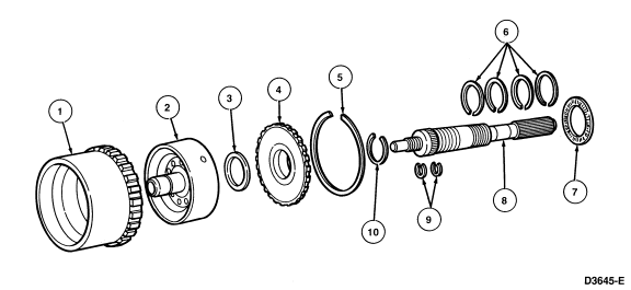
| Item |
Part Number |
Description |
|
1
|
7A153
|
Ring Gear
|
|
2
|
7F283
|
Direct Clutch Cylinder
|
|
3
|
7F240
|
Number 8 Needle Bearing
|
|
4
|
7D164
|
Output Shaft Hub
|
|
5
|
97713
|
Hub to Ring Gear Snap Ring
|
|
6
|
7F273
|
Seal Rings (4 Req'd)
|
|
7
|
7F242
|
Number 9 Needle Bearing
|
|
8
|
7060
|
Output Shaft
|
|
9
|
7F284
|
Steel Seal Rings (2 Req'd)
|
|
10
|
388104
|
Output Shaft to Hub Retaining Snap Ring
|
Disassembly
- Remove the ring retaining the output shaft hub to the ring gear.
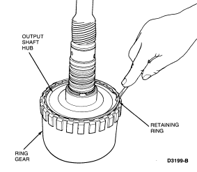
- Separate the output shaft and hub assembly from the ring gear.
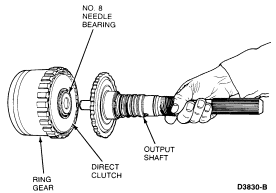
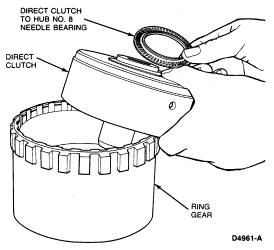
- Remove the direct clutch from the ring gear and the No. 8 needle bearing
from the back of the direct clutch.
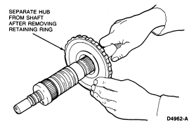
- Remove the four output shaft seal rings and the hub-to-output shaft
retaining ring. Separate the hub from the output shaft.
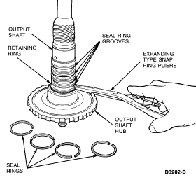
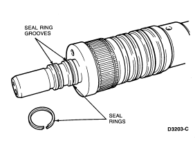
- Remove the two direct clutch seal rings from the output shaft.
Assembly
- Install two direct clutch seal rings.

- Install output shaft hub.
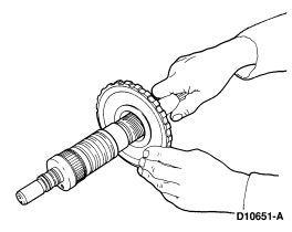
- Install four output shaft seal rings and hub-to-output shaft retaining ring.

- Install direct clutch and No. 8 needle bearing.

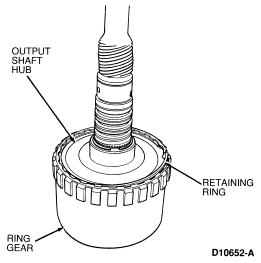
- Install output shaft and hub assembly to ring gear.

- Install output shaft-to-ring gear retaining ring.
Governor

| Item |
Part Number |
Description |
|
1
|
7A303
|
Governor Plug
|
|
2
|
7A302
|
Governor Valve Spring
|
|
3
|
7E242
|
Governor Oil Screen
|
|
4
|
7C063
|
Governor Body Assy
|
|
5
|
7A301
|
Governor Valve Body Cover
|
|
6A
|
N800274
|
Governor Cover Bolt (2 Req'd)
|
|
7B
|
N800273
|
Governor Counterweight Bolts (2 Req'd)
|
|
8
|
7C054
|
Governor Valve
|
|
9
|
—
|
E-Clip, Part of 7C054 Governor Valve
|
|
10
|
7A304
|
Governor Sleeve
|
|
11
|
7A189
|
Governor Counterweight
|
|
A
|
|
Tighten to 2.3-3.4 Nm (21-30 Lb-In)
|
|
B
|
|
Tighten to 6-7 Nm (54-61 Lb-In)
|
Disassembly
- Remove the screws retaining the counterweight to the governor body.
- Remove the cover screws and cover.
- Remove the plug, sleeve and governor valve from the governor body.
- Remove screen from governor body.
Assembly
- If removed, install the clip and spring on the governor valve.
- Install governor valve in governor body.
- Install the sleeve in the governor body with the points outward.
- Install the plug in the sleeve with the knurled face inward.
- Position the cover and install the retaining screws. Tighten the retaining
screws to 2.3-3.4 Nm (21-30 lb-in).
NOTE: The steel band (brass colored) goes inward and the top of the screen
faces outward.
- Install the screen in the body.
NOTE: The finished face of the governor body should be flush with the face of
the counterweight. (If it is not, the body is installed backwards.)
- Position the governor body on the counterweight and install the retaining
screws.
Tighten retaining screws to 6-7 Nm (54-61
lb-in).
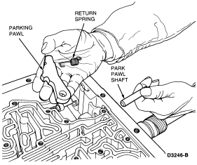
Parking Pawl
Removal
- Slide the park pawl shaft out the rear of the case and remove the parking
pawl.
- Remove the return spring.
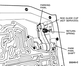
Installation
- Hook the squared end of the spring into the notch on the park pawl.
- Hold pawl and spring in place and hook curved end of spring into the recess
in the case.
- Install the park pawl shaft.
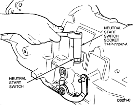
Neutral Start Switch
Tools Required:
- Neutral Start Switch Socket T74P-77247-A
Removal
- Using the Neutral Start Switch Socket T74P-77247-A, remove switch from case.
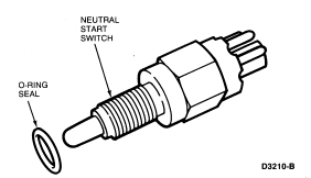
- Remove the O-ring seal and discard.
Installation
- Install a new seal on the neutral start switch.
- Install the switch in the case using the Neutral Start Switch Socket
T74P-77247-A. Tighten to 11-15 Nm (8-11 lb-ft).
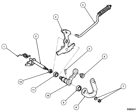
Manual and Throttle Linkage
| Item |
Part Number |
Description |
|
1
|
7F292
|
Throttle Lever Torsion Spring
|
|
2
|
7F290
|
Inner Throttle Lever and Shaft Assy
|
|
3
|
7A115
|
Inner Manual Lever
|
|
4
|
7A232
|
Parking Pawl Actuating Rod
|
|
5
|
7B210
|
Manual Lever Retaining Pin
|
|
6
|
7341
|
Grommet
|
|
7
|
N62004-S51
|
Throttle Lever Retaining Nut and Washer
|
|
8
|
2F291
|
Outer Throttle Lever
|
|
9
|
7F337
|
Throttle Lever Oil Seal
|
|
10
|
7F338
|
Outer Manual Lever
|
|
11
|
7B498
|
Manual Lever Shaft Oil Seal
|
|
12
|
N800287-S51
|
Manual Lever Retaining Nut
|
Tools Required:
- Puller T58L-101-B
- Impact Slide Hammer T59L-100-B
- Shift Shaft Seal Replacer T74P-77498-A
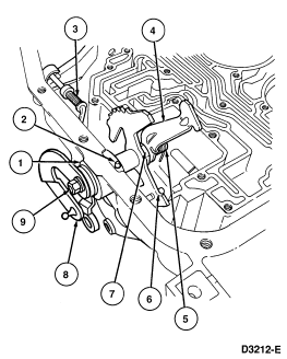
NOTE: Before disassembling the linkage, observe the location of the various
levers.
| Item |
Part Number |
Description |
|
1
|
7F338
|
Outer Manual Lever
|
|
2
|
7B210
|
Manual Lever Retaining Pin
|
|
3
|
7A232
|
Parking Pawl Actuating Rod
|
|
4
|
7F290
|
Inner Throttle Lever
|
|
5
|
7F292
|
Throttle Lever Torsion Spring
|
|
6
|
7A115
|
Inner Manual Lever
|
|
7
|
N800287-S51
|
Manual Lever Retaining Nut
|
|
8
|
2F291
|
Outer Throttle Lever
|
|
9
|
N62004-S51
|
Throttle Lever Retaining Nut
|
Disassembly
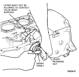
- Grasp the outer throttle lever firmly and loosen the lever retaining nut.
 CAUTION: The outer throttle lever must be held in the position shown to prevent
the inner throttle lever from rotating against the machined valve body surface.
Failure to observe this precaution could result in damage to the valve body
surface.
Remove the retaining nut, the lockwasher, and throttle lever.
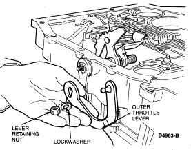
- Using a small screwdriver or awl, remove the seal from the outer manual
lever counterbore. Discard seal.
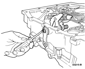
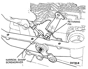
- Using a narrow, sharp screwdriver, carefully remove the manual shaft
retaining pin from the case.
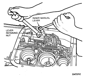
- Slide a 5/8-inch box end wrench over the inner manual lever, close to the
bottom of the lever. Do not allow the wrench to contact the "rooster comb"
area. Using a 21mm wrench, remove the manual lever retaining nut while securely
holding the inner manual lever.
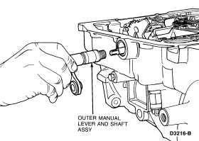
Thread the nut off the shaft and remove the lever.
- Remove the inner throttle lever and TV lever torsion spring.
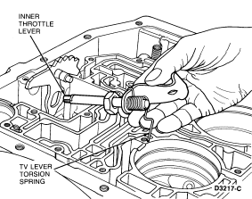
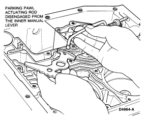
- Remove the inner manual lever and parking pawl actuating rod as an assembly.
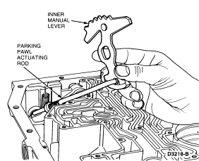
After removal, the rod may be disengaged from the lever.
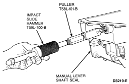
- Remove the manual lever shaft seal from the case using Puller T58L-101-B
and Impact Slide Hammer T59L-100-B. Discard seal.
Assembly
To assemble the manual throttle linkages, reverse the disassembly except
for the following:
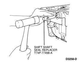
- Install a new manual lever seal using Shift Shaft Seal Replacer
T74P-77498-A.
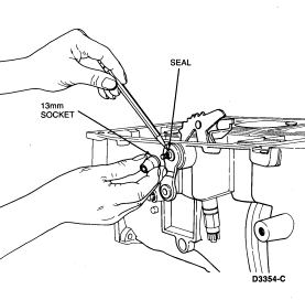
- Before installing the outer throttle lever, install a new seal in the outer
manual lever. To seat the seal, a 13mm thin wall socket may be used. Position
the ratchet end of the socket against the seal.
NOTE: The seal identification number must face outward.


 CAUTION: The piston bleed hole must be located at 12 o'clock position (toward
top of transmission).


 CAUTION: The outer throttle lever must be held in the position shown to prevent
the inner throttle lever from rotating against the machined valve body surface.
Failure to observe this precaution could result in damage to the valve body
surface.


