Section 03-01B: Engine, 5.0L HO and 5.0L Cobra | 1993 Mustang Workshop Manual |
Tools Required:
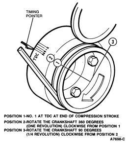
The valve arrangement of the LH bank is E-I-E-I-E-I-E-I and of the RH bank is I-E-I-E-I-E-I-E.
A 1.52mm (0.060-inch) shorter push rod or a 1.52mm (0.060 inch) longer push rod is available for service to provide a means of compensating for dimensional changes in the valve mechanism. Refer to the Master Parts List or the Specifications listed for the pertinent color code.
Valve stem-to-valve rocker arm clearance should be within specification with the hydraulic tappet completely collapsed. Repeated valve reconditioning operations (valve and/or valve seat refacing) will decrease the clearance to the point that, if it is not compensated for, the hydraulic valve tappet will cease to function and the valve will be held open.
The valve stem-to-valve rocker arm clearance is not adjustable. However, to obtain the specified valve clearance, it is important that all valve components be in a serviceable condition and installed and tightened properly.
To determine whether a shorter or a longer push rod is necessary, make the following check:
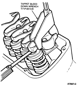
NOTE: Tappet Bleed Down Wrench T71P-6513-B will not fit on the Mustang Cobra roller rocker arms.
NOTE: If the clearance is less than specification, install a shorter push rod. If the clearance is greater than specification, install a longer push rod.