Section 12-00: Climate Control System—Service | 1993 Mustang Workshop Manual |
DIAGNOSIS AND TESTING
Refrigerant System Diagnostics
Tools Required:
- Rotunda A/C Service Kit 063-00010
- Rotunda Leak Detector 055-00014
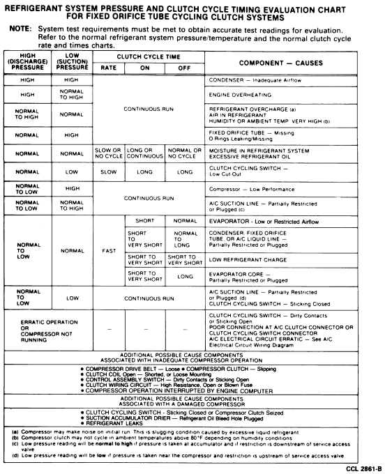
The best way to diagnose a concern in the refrigerant system is to note
the system pressures (shown by the manifold gauges), and the clutch cycle rate
and times. Then, compare the findings to the charts shown in the following
charts.
Normal Fixed Orifice Tube Cycling Clutch Refrigerant System
Pressure/Temperature Relationships
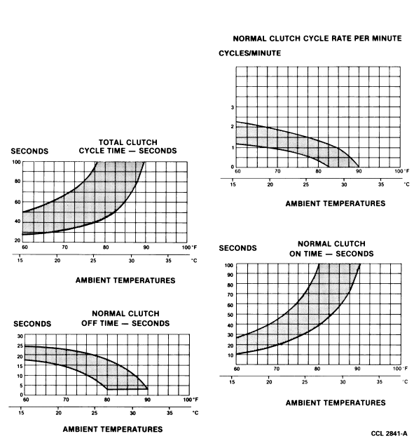
Normal Clutch Cycle Rates and Times—Fixed Orifice Tube
System
- The system pressures are low (compressor suction) and high (compressor
discharge).
- A clutch cycle is the time the clutch is engaged plus the time it is
disengaged (time on plus time off).
- Clutch cycle times are the combined lengths of time (in seconds) that the
clutch is ON and OFF.
The following procedure is recommended for achieving accurate diagnosis
results in the least amount of time.
- Connect a manifold gauge set, part of Air Conditioning Service Tool Kit
063-00010 or an equivalent, to the system. Purge air from red and blue hoses
using system pressure by loosening fittings at gauge set. Open only long enough
for air to escape and then tighten fittings.
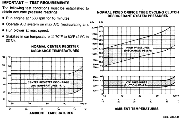
NOTE: The test conditions, specified at the top of each chart, must be met to
obtain accurate test results.
- Start engine and turn ON A/C system.
- As soon as the system is stabilized, record the high and low pressures as
shown by the manifold gauges. Normally the suction pressure should decrease to
a range between 22 and 28 psi and the pressure switch should open. When the
pressure switch opens, the suction pressure should start to rise to a range
between 40 and 47 psi. Somewhere between 40 and 47 psi, the pressure switch
should close and the suction pressure should start to drop.
The discharge (high) pressure should operate the reverse of
the suction pressure. When the suction pressure is dropping, the discharge
pressure should increase. When the suction pressure is increasing, the
discharge pressure should decrease.
- Determine the clutch cycle rate per minute (clutch on time plus off time is
a cycle).
- Record clutch off time in seconds.
- Record clutch on time in seconds.
- Record center register discharge temperature.
- Determine and record ambient temperatures.
- Compare test readings with previous applicable charts.
- Plot a vertical line for recorded ambient temperature from scale at
bottom of each chart to top of each chart.
- Plot a horizontal line for each of the other test readings from scale at
LH side of appropriate chart.
Additional cause components are listed for poor compressor operation or a
damaged compressor condition at the bottom of the following evaluation chart.
Refrigerant System and Clutch Cycle Rate and Timing
Evaluation—Fixed Orifice Tube Systems