Steering ColumnŚInstallation
Section 11-04: Steering Column | 1993 Mustang Workshop Manual |
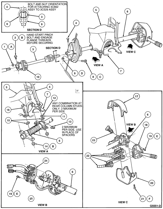
The column is attached to the brake pedal support bracket by two collar-type brackets bolted to flanges on the brake support. The lower column retaining collar is a sintered iron ring with protrusions within the ring. The protrusions act as a die which deforms the outer tube as the column collapses. Any extrusion of the outer tube through the iron ring die requires that the outer tube and mounting brackets be replaced as an assembly. Refer to the illustrations for exploded views and nomenclature.
The key release button functions to prevent inadvertent locking of the
steering wheel. The release button is located on the lower LH of the steering
column below the turn signal lever. The ignition switch cannot be rotated to
the LOCK position until the release button is pushed.
Steering ColumnŚInstallation
| Item | Part Number | Description |
|---|---|---|
| 1A | 34977-S2 | Nut (2 Req'd) |
| 2B | 385970-S100 | Bolt |
| 3 | 3C662 | Shaft Assy |
| 4 | 58655-S2 | Bolt |
| 5 | Ś | Brake Pedal Support |
| 6 | 3C529 | Column Assy |
| 7 | Ś | Lateral Brace |
| 8C | 388489-S9 | Bolt (4 Req'd) |
| 9D | 388795-S100 | Nut |
| 10 | 3B676 | Bolt |
| 11 | N801256-S2 | Spacer |
| 12 | N630069-S2 | Spacer |
| 13 | 3R665 | Spacer (Optional) |
| 14C | 55738-S2 | Nut (4 Req'd) |
| 15 | 377689-S2 | Retainers (2 Req'd) |
| 16 | 389771-S2 | Stud (2 Req'd) |
| 17 | 3530 | Upper Shroud |
| 18 | 13K359 | Switch Assy |
| 19E | 390345-S36 | Screw (2 Req'd) |
| 20 | 3533 | Lower Shroud |
| 21F | 55929-S2 | Screw (2 Req'd) |
| 22 | 14489 | Wiring Assy |
| 23 | 11582 | Lock Cylinder |
| 24 | 14A664 | Contact Assy |
| A | Ś | Tighten to 34-46 Nm (25-34 Lb-Ft) |
| B | Ś | Tighten to 29.7-40.3 Nm (22-30 Lb-Ft) |
| C | Ś |
Tighten to 1.6-2.2 Nm (14-19 Lb-In) |
| D | Ś | Tighten to 53.1-71.9 Nm (39-53 Lb-In) |
| E | Ś | Tighten to 2-3 Nm (14-26 Lb-In) |
| F |
Tighten to 0.6-1.0 Nm (5.3-9 Lb-In) |
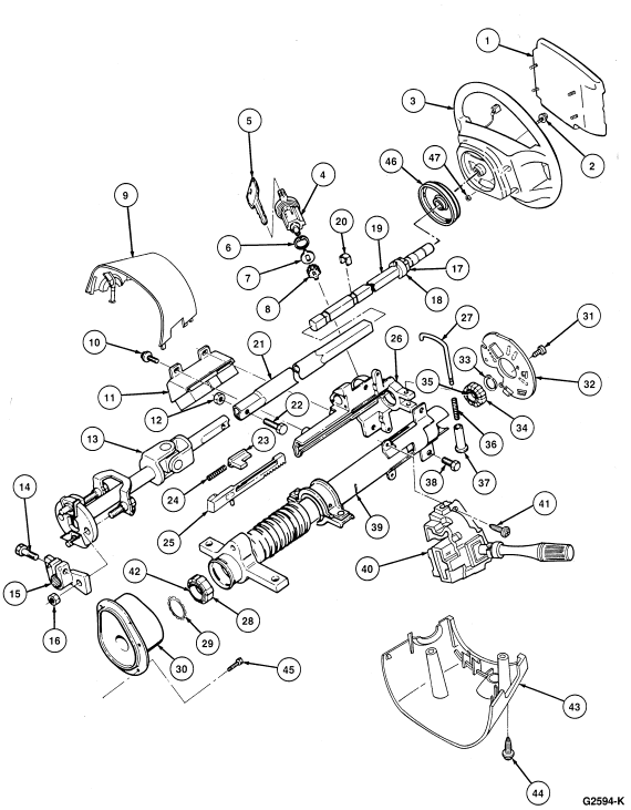
| Item | Part Number | Description |
|---|---|---|
| 1 | 043B13 | Air Bag Module Assy |
| 2 | N804395-S100 | Bolt |
| 3 | 3600 | Wheel Assy Ś Stng. |
| 4 | 11582 | Lock Cyl. |
| 5 | Ś | Key (Body) |
| 6 | 3F579 | Retainer |
| 7 | 3E700 | Bearing |
| 8 | 3E717 | Gear Ś Stng. Col. Lock |
| 9 | 3530 | Shroud Ś Upper |
| 10 | N804855-S100 | Bolt (2 Req'd) |
| 11 | 11572 | Switch Assy Ś Ignition |
| 12 | 388795-S100 | Nut Ś 7/16-14 Hex Lock |
| 13 | 3C662 | Shaft Assy Ś Stng. Col. Lower |
| 14 | 385970-S100 | Bolt Ś 3/8-24 x 1.22 |
| 15 | 3459 | Flange Ś Stng. Shaft Lower |
| 16 | 34977-S2 | Nut Ś 3/8-16 Hex Lock |
| 17 | 13318 | Cam Ś Turn Sig. Turn Off |
| 18 | 3B767 | Lock Ś Stng. Col. Position |
| 19 | 3A527 | Shaft Ś Stng. Gear Upper |
| 20 | 3E629 | Anti-Rattle Clips (2 Req'd) |
| 21 | 3E628 | Shaft Ś Stng. Gear Lower |
| 22 | 58655-S2 | Bolt Ś 7/16-14 x 1.50 Hex |
| 23 | 3E691 | Pawl Ś Stng. Col. Lock |
| 24 | 3E696 | Spring Ś Stng. Col. Lock |
| 25 | 3E723 | Actuator Assy Ś Stng. Col. Lock |
| 26 | 3F643 | Housing Ś Stng. Col. Lock Cyl. |
| 27 | 3F528 | Lever Ś Stng. Col. Lock Actuator |
| 28 | 3E733 | Bearing Assy Ś Stng. Gear Shaft Lower |
| 29 | 3F543 | Ring Ś Stng. Gear Shaft Lower Bearing Retainer |
| 30 | 3E735 | Boot AssyŚStng. Col. |
| 31 | 390345 | Screw Ś No. 8-18 x .62 Pan Hd. Tap (2 Req'd) |
| 32 | 3C610 | Retainer Ś Stng. Col. Upper Bearing |
| 33 | Ś | Snap Ring |
| 34 | 3518 | Sleeve Ś Stng. Col. Upper Bearing |
| 35 | 3517 | Bearing Assy Ś Stng. Col. Upper |
| 36 | 3E696 | Spring Ś Stng. Col. Lock |
| 37 | Ś | Knob Ś Stng. Col. Lock Actuator |
| 38 | N605531-S2 | Bolt Ś M8 x 1.25 Hex Hd. (2 Req'd) |
| 39 | 3A617 | Tube Assy Col. Outer |
| 40 | 13K759 | Multi-Function Switch |
| 41 | 52794-S2 | Screw Ś No. 8-18 x .62 Pan Hd. Tap (2 Req'd) |
| 42 | 3A649 | Sleeve Ś Steering Column Lower Bearing |
| 43 | 3530 | Shroud Ś Stng. Col. Lower |
| 44 | 55929-S2 |
Screw Ś No. 8-18 x 1.00 Pan Hd. Tap (2 Req'd) |
| 45 | 388489-S2 | Screw (4 Req'd) |
| 46 | 14A664 | Contact Ring |
| 47 | N621903-S2 | Nut and Washer Assy |