2.3L Engine
Section 06-03: Brakes, Front Disc | 1993 Mustang Workshop Manual |
The caliper assembly consists of a pin slider-type caliper housing, inner and outer shoe and lining assemblies, and a single piston. The caliper assembly slides on two locating pins which also act as the retaining bolts between the caliper and the combination anchor plate and spindle.
The caliper housing contains a single piston. The piston has a moulded rubber dust boot on its outer end that attaches to a cylinder bore groove to prevent cylinder contamination. There is also a rectangular section rubber piston seal located in the cylinder bore providing sealing between the cylinder and piston.
A groove is cut inside the piston for inner brake shoe clip retention.
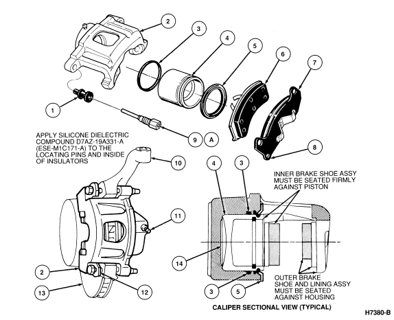
2.3L Engine
| Item | Part Number | Description |
|---|---|---|
| 1 | 2B299 | Insulator |
| 2 | 2B119 LH 2B118 RH |
Caliper Assy |
| 3 | 2B115 | Piston Seal |
| 4 | 2196 | Piston |
| 5 | 2207 | Dust Boot |
| 6 | 2019 RH 2C046 LH |
Inner Shoe |
| 7 | 2018 RH 2C088 LH |
Outer Shoe |
| 8 | Ś | Indicator Tab |
| 9A | 2B296 | Locating Pin |
| 10 | Ś | Spindle-Anchor Plate |
| 11 | 2208 | Bleed Screw |
| 12 | 2C088 LH 2018 RH |
Outer Shoe and Lining |
| 13 | 1K002 | Rotor |
| 14 | Ś | Caliper Housing |
| A | Tighten to 61-88 Nm (45-65 Lb-Ft) |
The caliper assembly is attached to the spindle with an internal drive caliper pin. These pins require the use of a Torx ® Drive Bit D79P-2100-T50 or equivalent for removal or installation. The later pins act as a support for the outer shoe and lining assemblies.
The outer brake shoe and lining assembly are longer than the inner shoe and lining assembly.
The outer shoe and lining assemblies are attached to the caliper by a spring clip riveted to the shoe surfaces.
A metal wear indicator is attached to the outer shoe and lining assembly. This indicator emits a noise when the lining is worn to a point where replacement is necessary. Because of the metal wear indicator, the outer shoes are RH or LH and must not be interchanged.
The inner shoe and lining use a three-finger anti-rattle clip and a shoe insulator held in position by the clip rivet. The inner shoes are RH or LH and should not be interchanged.
Two rubber insulators are installed in the caliper attaching holes. The
insulators prevent metal-to-metal contact between the locating pins and the
caliper. The brake hose inlet port thread size is either 12mm or 14mm (0.47 or
0.55 inch).
5.0L Engine
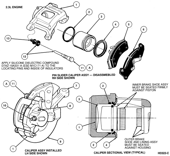
| Item | Part Number | Description |
|---|---|---|
| 1 | 2B119 LH 2B118 RH |
Caliper Assy |
| 2 | 2B115 | Piston Seal |
| 3 | 2196 | Piston |
| 4 | 2207 | Dust Boot |
| 5 | 2019 RH 2C046 LH |
Inner Shoe |
| 6 | 2018 RH 2C008 LH |
Outer Shoe |
| 7 | Ś | Spindle-Anchor Plate |
| 8 | Ś | Inlet Port |
| 9 | 2K004-5 | Shield |
| 10 | Ś | Bleed Screw |
| 11A | Ś | Caliper Locating Pins (2 Req'd) |
| 12 | D7AZ-19A331-A (ESE-M1C171-A) | Apply Silicone Dielectric Compound to the Locating Pins and Inside of Insulators |
| 13 | 2B299 | Insulator |
| A | Tighten to 61-88 Nm (45-65 Lb-Ft) |
The caliper assembly is attached to the same spindle with a hex head type pin. The outer brake shoe and lining assembly is longer than the inner shoe and lining assembly. Both inner and outer shoe lining assemblies are attached to the caliper by spring clips. The outer clip is riveted to the lining assembly. The inner clip is riveted to the lining assembly as a separate item. The inner shoe is attached to the caliper by installing the spring clip to the inside of the caliper piston. The outer shoe clips directly to the caliper housing. Two rubber insulators are installed in the caliper attaching holes. The insulators prevent metal-to-metal contact between the locating pins and the caliper.