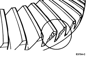
Damaged Gear Teeth
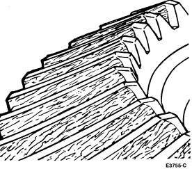
Scored Gear Teeth
Section 05-00: Axle and Driveshaft—Service | 1993 Mustang Workshop Manual |
Gear Howl and Whine
Before disassembling the axle to diagnose and correct gear noise, it is important that the tires, exhaust, trim items, roof racks and axle shafts/wheel bearings be checked as possible causes.
The noises described under Road Test usually have specific causes that can be diagnosed by observation as the unit is disassembled. The initial clues are, of course, the type of noise heard on the road test and the driving conditions.
Chuckle
Chuckle that occurs on the coast driving phase is usually caused by excessive clearance between the differential gear hub and the differential case bore, or by a damaged tooth on the coast side of the pinion or ring gear.
Any damage to a gear tooth on the coast side can cause a noise identical to chuckle. Even a very small tooth nick or ridge on the edge of a tooth is enough to cause the noise.
You can often correct this condition and eliminate the noise simply by cleaning up the gear tooth nick or ridge with a small grinding wheel. If the cleaned up or damaged area is larger than 3.2mm (1/8 inch), it is advisable to replace the gearset.
To check the gearset, remove as much lubricant as possible from the gears with clean solvent. Wipe the gears dry or blow them dry with compressed air. Look for scored or damaged teeth. Also look for cracks or other damage.
If either gear is scored or damaged badly, the gearset must be replaced.
Also, if there is metal broken loose, the carrier and housing must be cleaned
to remove particles that could cause damage later. Any other damaged parts in
the axle must be replaced.
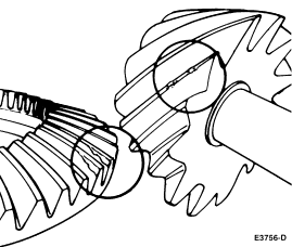
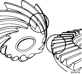
Damaged Gear Teeth
Scored Gear Teeth
Knock
Knock, which can occur on all driving phases, has several causes. In most cases, you will discover one of the following conditions:
Another possibility is simply that one or more bolts are slightly backed-out. Remove, replace and properly tighten the bolts using Stud and Bearing Mount E0AZ-19554-BA (WSK-M2G349-A1) or equivalent, on the threads.
NOTE: Be sure to measure the end play with a dial indicator, not by feel. A guess usually feels like far more end play than there actually is.
Clunk
Clunk is due to backlash in the driveline or loose rear suspension components. To determine whether driveline clunk is caused by the axle, make a check of the total axle backlash as follows.
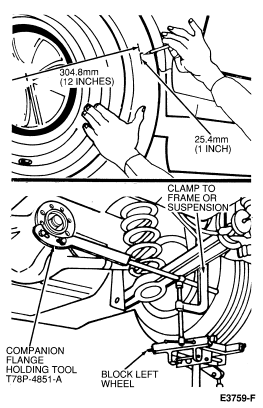
If the backlash is within this limit, the clunk will not be eliminated by going into the axle.
Check for these conditions if the backlash is excessive.
If none of the above conditions show up, there may be a loose fit of the axle shafts to the side gear splines. You should continue as follows until the correction is made.
Bearing Noise
Bearing malfunctions will normally be obvious at disassembly. As noted earlier, pinion bearings make a high-pitched, whistling noise, usually at all speeds. However, if there is only one pinion bearing that is malfunctioning, the noise may vary in different driving phases.
Pinion bearings are frequently replaced on axles with low mileage under 24,139 km (15,000 miles), unnecessarily when correcting gear noise. They should not be replaced unless they are actually scored or damaged, or there is a specific pinion bearing noise. Examine the large end of the rollers for wear. If the bearings original blend radius has worn to a sharp edge, the bearing should be replaced.
Remember that the low-pitched rumble of a malfunctioning wheel bearing can be duplicated by an exterior luggage rack or by tires.
Wheel bearing noise might be mistaken for pinion bearing noise, so be
sure to look at the wheel bearings carefully before tearing down the axle. 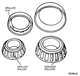
Wheel bearings are pressed into the axle housing tubes, making them more
difficult to check. However, the axle shaft is the inner race for the bearing.
If the bearing is damaged, the roller surface on the axle shaft may be damaged
as well. The rollers run on approximately the center of the polished surface. 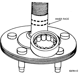
Bearing Preload Check
The absence of differential bearing preload causes noise as driving loads tend to move the gear pattern out of position.
Both the pinion bearing and differential bearing preload must be checked to ensure that the pattern will stay in place under load.
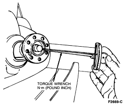
Check the pinion bearing preload by removing wheels and brake drums and putting a Nm (lb-in) torque wrench on the pinion nut and measuring the torque effort it takes to turn the pinion. Compare the reading with the preload specification for used bearings. Refer to Section 05-02A or Section 05-02B for specifications.
NOTE: These preload readings are to be made when the axle assembly is at room temperature or above. Cold lube will give a false reading.
If any end play or radial play can be detected when applying a force by hand, the pinion bearings are not preloaded.
NOTE: The absence of preload here may indicate that one or more of the components (i.e., bearings, slinger spacer or flange) is worn or damaged.
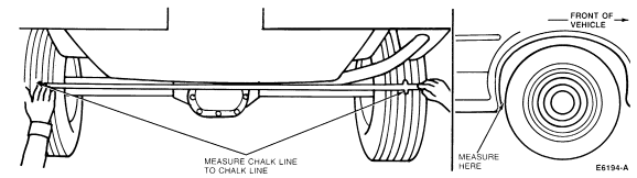
Bent Axle Housing—Analysis
It is important to check for a bent axle housing anytime a vehicle has sustained structural damage or unusual tire wear is noted. A quick check can be performed any time damage to the rear axle housing is suspected.
Axle Alignment Inspection, Rear
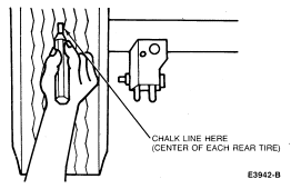
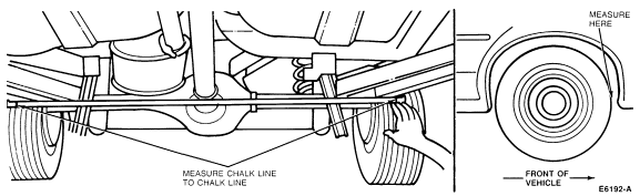
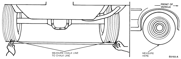
Example:
Toe in occurs when the front reading is less than the rear reading.
Example:
Positive (+) camber is when the bottom reading is less than the average of the front and rear readings. Negative (-) camber is when the bottom reading is greater than the average of the front and rear readings.
If the rear axle assembly does not meet this specification, it must be replaced.