Section 02-03: Engine and Transmission Mounting | 1993 Mustang Workshop Manual |
REMOVAL AND INSTALLATION
Engine Insulators
2.3L Engines
These procedures apply to a RH or LH installation.
NOTE: Whenever self-locking mounting bolts and nuts are removed, they must be
replaced with new self-locking mounting bolts and nuts. Prior to installing new
self-locking mounting bolts (adhesive on threads), hardened residual bolt
adhesive must be removed from the engine block bosses with an M10 X 1.5
bottoming tap.
Removal
- Support the engine using a wood block and jack placed under the engine.
- Remove the through bolts retaining both insulators to the No. 2 crossmember
pedestal bracket. On convertible, remove nuts.
- Disconnect shift linkage.
- Raise the engine sufficiently to disengage the insulator from the
crossmember pedestal bracket.
- Remove the bolts retaining the insulator and bracket assembly to the
engine. Remove the insulator and bracket assembly.
Installation
- Position the insulator and bracket assembly to the engine. Install the
retaining bolts. Tighten to 47-63 Nm (35-46 lb-ft).
- Lower the engine into position. Ensure that the insulators are seated flat
on the No. 2 crossmember. Hand start bolts, lower engine completely, then
tighten through bolts to 97-133 Nm (72-98 lb-ft).
- Tighten insulator-to-crossmember nuts to 98-144 Nm (73-106
lb-ft). On sedars, tighten insulator-to-crossmember bolt to 47-63 Nm
(35-46 lb-ft).
- Install shift linkage.
5.0L Engines
The front supports are located on each side of the cylinder block. The
procedures given apply to either a RH or LH installation. Whenever
self-locking mounting bolts and nuts are removed, they must be replaced with
new self-locking bolts and nuts.
Removal
- Remove fan shroud attaching screws.
- Support the engine using a jack and wood block placed under the engine.
- Remove the nuts attaching insulators to the No. 2 crossmember.
- Disconnect shift linkage (AOD transmission).
- Raise the engine sufficiently with the jack to disengage the insulator
studs from the crossmember.
- Remove transmission brace attached at RH engine mount bracket, if so
equipped.
- Remove the engine insulator and bracket assembly to cylinder block
attaching bolts.
- Remove the engine insulator assembly.
Installation
- Position the insulator assembly on the engine and install the attaching
bolts. Tighten the bolts to 60-81 Nm (45-59 lb-ft).
- Attach transmission brace to RH engine mount bracket, if so equipped.
Tighten nut to 60-81 Nm (45-59 lb-ft).
- Lower the engine into position. Ensure that the insulators are seated flat
on the No. 2 crossmember and the insulator studs are at the bottom of the
slots. Start the insulator-to-crossmember nuts and tighten to 98-144 Nm
(73-106 lb-ft).
- Install the fan shroud attaching screws. Tighten to 3-5 Nm
(27-44 lb-in).
- Connect shift linkage (AOD transmission).
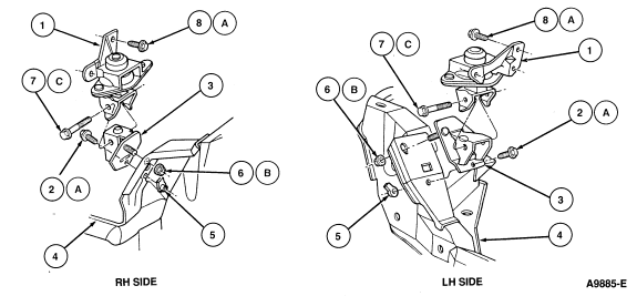
Sedan with 2.3L Multiport Fuel Injection (MFI)

Item |
Part Number |
Description |
|
1
|
6C010(RH)
6C060(LH)
|
Engine Insulator Assy
|
|
2A
|
N803098-S2
|
Bolt
|
|
3
|
6028(RH)
6029(LH)
|
Engine Insulator Bracket Assy
|
|
4
|
—
|
Number 2 Crossmember
|
|
5
|
N803018-S2
|
Nut
|
|
6B
|
N803226-S19D
|
Nut
|
|
7C
|
N802838-S2
|
Bolt
|
|
8A
|
N605799-S100
|
Bolt (3 Req'd)
|
|
A
|
|
Tighten to 47-63 Nm (35-46 Lb-Ft)
|
|
B
|
|
Tighten to 98-144 Nm (72-106 Lb-Ft)
|
|
C
|
|
Tighten to 97-133 Nm (72-98 Lb-Ft)
|
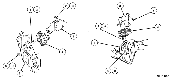
Convertible With 2.3L MFI

| Item |
Part Number |
Description |
|
1A
|
N605919-S2
|
Bolt
|
|
2B
|
N605799-S100
|
Bolt (3 Req'd)
|
|
3
|
6043(RH)
6A069(LH)
|
Engine Insulator Assy
|
|
4
|
6038(RH)
6B032(LH)
|
Engine Insulator Bracket Assy
|
|
5
|
—
|
Number 2 Crossmember Assy
|
|
6C
|
N803226-S190
|
Nut
|
|
7
|
—
|
Bolt
|
|
A
|
|
Tighten to 40-60 Nm (30-44 Lb-Ft)
|
|
B
|
|
Tighten to 34-47 Nm (25-35 Lb-Ft)
|
|
C
|
|
Tighten to 98-144 Nm (72-106 Lb-Ft)
|

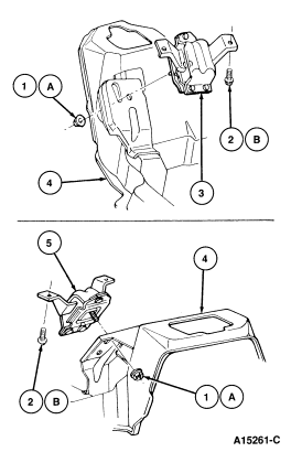
Item |
Part Number |
Description |
|
1A
|
N803226-S190
|
Nut
|
|
2B
|
391162-S100
|
Bolt
|
|
3
|
6038
|
Mount Assy RH
|
|
4
|
|
No. 2 Crossmember Assy
|
|
5
|
6B032
|
Mount Assy LH
|
|
A
|
|
Tighten to 98-144 Nm (73-106 Lb-Ft)
|
|
B
|
|
Tighten to 60-81 Nm (45-59 Lb-Ft)
|


